


9
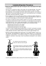
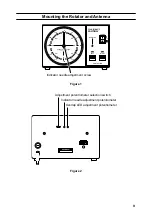
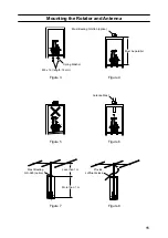
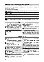
Mounting the Rotator and Antenna
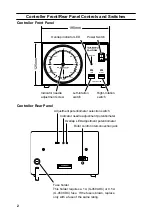
W
S
SE
NE
SW
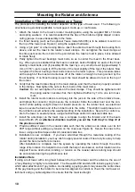
AZIMUTH INDICATOR
EACH DIVISION 5ー
NW
E
270
300
240
330
210
180
0°
90
60
120
30
150
G-450A
OFF
ON
LEFT
RIGHT
OVERLAP
CONTROLLER
POWER
Indicator needle adjustment screw
Figure 1
Adjustment potentiometer selection switch
Indicator needle adjustment potentiometer
Overlap LED adjustment potentiometer
Figure 2


