manualshive.com logo in svg
background image

16

Safety Precautions (Be Sure to Read)

Yaesu is not liable for any failures or problems caused by the use or misuse of this product 

by the purchaser or any third party. Also, Yaesu is not liable for damages caused through the 

use of this product by the purchaser or any third party, except in cases where ordered to pay 

damages under the laws.

Types and meanings of the marks


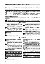
WARNING

This mark indicates a potentially hazardous situation, which, if not avoid-

ed, could result in death or serious injury.


CAUTION

This mark indicates a potentially hazardous situation, which, if not avoid-

ed, may result in minor or moderate injury or only property damage. 

Types and meanings of symbols

These symbols signify prohibited actions, which must not be done to use this product 

safely.

These symbols signify required actions, which must be done to use this product safely.

 WARNING

Please read this user manual thoroughly and famil-

iarize yourself with the correct installation proce-

dure before starting installation.

Installing this product requires work to be undertaken 

high above ground. Performing work with which you are 

unfamiliar can lead to fatal accidents due to falling.

Similarly, failing to install the product correctly can be 

a cause of the antenna and associated equipment 

collapsing, resulting in a fatal accident or damage to 

houses or other property. Accordingly, always check all 

safety considerations before starting work.

Always wear a safety harness when working high 

above ground.

Failure to use a safety harness can be a cause of death 

or serious injury.

Never disassemble or modify the unit.

When working high above ground, ensure that there 

are no people at ground level.

Dropping tools, bolts, or other parts could result in 

death or serious injury.

Ensure that the size of the antenna attached to this 

product is within the specifications listed in this 

manual.

Attaching an antenna that is larger than allowed by the 

specifications can be a cause of the antenna and asso-

ciated equipment collapsing, resulting in a fatal accident 

or damage to houses or other property.

Ensure that the bolts and other fasteners used for 

installation are tightened securely.

Failure to tighten bolts and other fasteners sufficiently 

can be a cause of the antenna and associated equip-

ment collapsing, resulting in a fatal accident or damage 

to houses or other property.

 CAUTION

When installing this product, take care not to jam 

your fingers between parts or cut fingers on edges 

of parts.
If the condition of the equipment is abnormal such 

as emitting smoke or an unusual smell, continuing 

to use the equipment may result in fire or malfunc-

tion.

In such cases, turn off the power immediately and un-

plug from the power socket.

After checking that the equipment is no longer emitting 

the smoke or unusual smell, return the product to the 

vendor or to your nearest Yaesu office or service center 

for repair.

In the event of foreign material getting inside the 

controller, turn off the power immediately and un-

plug from the power socket.

Continuing to use the product in this condition can re-

sult in fire or malfunction.

Do not use the product with a power supply voltage 

other than the specified voltage as this can cause 

fire or electric shock.
In the product is to remain unused for a long period 

of time, unplug the AC power cable from the AC 

wall outlet and Rotator Control Cable from the jack 

for safety.
Do not operate continuously for more than 3 min-

utes.

The equipment can be operated for up to 5 minutes but 

operation must be halted and the motor rested for at 

least 15 minutes afterwards.

Do not place the controller in direct sunlight or 

close to heaters as this can cause the box to distort 

or discolor.

Do not place the controller in humid or dusty envi-

ronments as this can cause fire or malfunction.

Do not place the controller in enclosed or poorly 

ventilated positions such as in a bookshelf as this 

can cause fire or faults.
Do not place the controller on carpet or bedding as 

this can cause heat to build up internally resulting 

in fire.
Do not place heavy objects on top of the controller 

as this can cause the controller to fall or tip over 

causing injury.
Do not place small metal objects such as paper 

clips on top of the controller as these can fall into 

the controller causing fire or malfunction.
Do not wipe the controller with solvents such as 

thinner or benzene as this can cause the box to dis-

tort or discolor.

Use only a soft, dry cloth to wipe stains from the case.

Do not turn on the power supply until rotator and 

controller setup is complete.

Содержание G-450ADC

Страница 1: ...G 450ADC G 450CDC Antenna Rotator Controller User Manual ...

Страница 2: ... kgf cm 217 ft lbs Maximum Vertical load Continuous load 100 kg or less Instantaneous load 300 kg Mast Outside Diameter φ32 to φ63 center protrudes by φ48 to φ52 Rotation Range 450 360 Rotation Time approx 56 seconds 20 Antenna K Coefficient 100 Wind Loading Area Pole type 0 5 m2 x 0 5 m Tower type 1 m2 Maximum Continuous Duty 3 minutes Rotor Dimensions and Weight φ186 x 263 mm approx 3 2 kg Contr...

Страница 3: ...eved using the GL 33 mast adjustment plate Not supplied with G 450ADC per the illustrations below Mast Diameter φ32 to φ38 Use two plates Mast Diameter φ39 to φ47 Use one plate Mast Diameter φ48 to φ50 Do not use a plate The use of a mast of outside diameter greater than 51 mm 2 01 will result in off center rotation The amount of offset increases with increasing mast diameter A mast of 60 mm outsi...

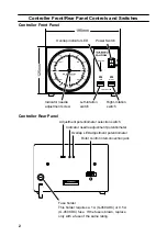
Страница 4: ...verlap indicator LED Indicator needle adjustment screw Left rotation switch Right rotation switch Power Switch 125mm Controller Rear Panel Adjustment potentiometer selection switch Indicator needle adjustment potentiometer Overlap LED adjustment potentiometer Rotor control interconnection jack Fuse holder This holder requires a 1 A G 450ADC or 0 5 A G 450CDC fuse If the fuse is blown replace only ...

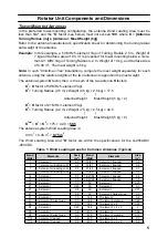
Страница 5: ...onal nut Rotator Attachment Plate Dimensions 8 4 m m 8 4 m m φ 1 1 9 φ9 4 locations The tower plate onto which the rotator unit is mounted must be drilled with four holes of 9 mm diameter equally spaced on a circle of 119 mm diameter The center to center dis tance between any two adjacent mounting holes is 84 mm ...

Страница 6: ...ned weight of antenna plus mast of 10 kg or less and the product of multiplying the Antenna Wind Load Area in m2 by the Height of the Antenna Mast in m must be 0 25 or less see Figure and Table 1 Antenna Weight Mast Weight 10 kg Antenna Wind Load Area Height of Antenna Mast 0 25 Refer to the antenna manufacturer s specification sheet for determining the weight and the surface area of the proposed ...

Страница 7: ...1 MHz 3 element Yagi K2 Turning Radius 4 2 m x Weight 7 5 kg 2 5 kg 42 0 Antenna Weight Mast Weight 5 kg 2 KTotal K1 K2 175 42 0 59 5 The antenna system Wind Loading Area is 0 3 m2 0 45 m2 0 75 m2 The Wind Loading Area and K factor are within the specifications for the G 450ADC 450CDC Table 1 Wind Loading Areas for Common Antennas Typical Band MHz Elements Area m2 Band MHz Elements Area m2 7 2 ele...

Страница 8: ...ciated with each pin for reference later Pins 1 6 and 7 of the round connector are not used Confirm that all solder joints are firm and cleanly made as this part of the cable will be difficult to access once the rotator is installed on top of the tower Do not slide the shell onto the connector at this time 5 Crimp the supplied pin contacts onto the wires on the opposite end of the cable per the il...

Страница 9: ... the wires with solder Make sure to insert the Water Resist Boot first 2 5 3 6 3 4 5 1 2 7 4 Terminal 1 6 and 7 are not used Assembly of 7 pin Metal Connector Pin 1 and 7 of the seven pin metal connector is not used as viewed from pin insertion side as viewed from solder side Wiring for the control cable identical numbers to be connected ...

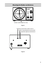
Страница 10: ...s to be pointing exactly to 0º If the indicator needle is not pointing exactly to 0º go to the rear panel of the controller and set the Adjust ment Potentiometer Selection Switch see Figure 2 to the right position Now use a small screwdriver to adjust the Indicator Needle Adjustment Potentiometer Fig 2 so that the in dicator needle points exactly to 0º 8 After aligning the needle to 0º set the Adj...

Страница 11: ...ION 5ー NW E 270 300 240 330 210 180 0 90 60 120 30 150 G 450A OFF ON LEFT RIGHT OVERLAP CONTROLLER POWER Indicator needle adjustment screw Figure 1 Adjustment potentiometer selection switch Indicator needle adjustment potentiometer Overlap LED adjustment potentiometer Figure 2 ...

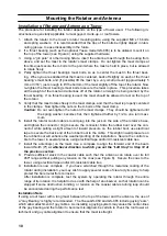
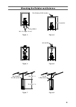
Страница 12: ...asher becomes flat then tightened further by 1 2 to one turn maxi mum 6 Install the rotator control cable s round plug into the jack on the side of the rotator s base and tighten the connector ring to secure the connector Slide the rubber boot over the con nector while putting a slight amount of inward pressure on the rubber boot use electrical tape to secure the back end of the rubber boot to the...

Страница 13: ...tenna Spring Washer Antenna Mast Mast Bearing GS 065 option Mast Bearing GS 065 option Must be parallel M8 x 16 length 16 mm Figure 3 Figure 4 Figure 5 Figure 6 Figure 7 Figure 8 Provide sufficient slack More than 1 m Less than 1 m ...

Страница 14: ...llation of suitable lightning arrestors on all control cables and coaxial lead in cables from your antenna installation See your dealer for details of available light ning protection devices If an electrical storm should be reported in your area quickly unplug the control cable from the rear of the rotator s controller box and disconnect the AC cable from the wall outlet Disconnect the coaxial cab...

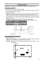
Страница 15: ...the terminals on the back of the controller etc and make corrections before replacing the 3A fuse on the board inside the controller CAUTION Only replace with a fuse of similar type and rating 3A To measure voltage between terminals remove the connection cable to the rotor Switch Pin Voltage Power switch is in the ON position 4 5 0 V Press the LEFT switch 4 5 DC 22 V Press the RIGHT switch 4 5 DC ...

Страница 16: ... cover any impairment caused by tampering misuse failure to follow instructions supplied with the product unauthorized modifications or damage to this product for any reasons such as accident excess moisture lightning power surges connection to improper voltage supply damage caused by inadequate packing or shipping procedures loss of damage to or corruption of stored data product modification to e...

Страница 17: ...e decision to repair or replace this product is the sole discretion of YAESU MUSEN Other conditions YAESU MUSEN S MAXIMUM LIABILITY SHALL NOT EXCEED THE ACTUAL PURCHASE PRICE PAID FOR THE PRODUCT IN NO EVENT SHALL YAESU MUSEN BE LIABLE FOR LOSS OF DAMAGE TO OR CORRUPTION OF STORED DATA OR FOR SPECIAL INCIDENTAL CONSEQUENTIAL OR INDIRECT DAMAGES HOW EVER CAUSED INCLUDING WITHOUT LIMITATION TO THE R...

Страница 18: ...n bolts and other fasteners sufficiently can be a cause of the antenna and associated equip ment collapsing resulting in a fatal accident or damage to houses or other property CAUTION When installing this product take care not to jam your fingers between parts or cut fingers on edges of parts If the condition of the equipment is abnormal such as emitting smoke or an unusual smell continuing to use...

Страница 19: ...t be disposed as household waste Electronic and Electrical Equipment should be recycled at a facility ca pable of handling these items and their waste by products Please contact a local equipment supplier representative or service cen ter for information about the waste collection system in your country ...

Страница 20: ...produced without the permission of YAESU MUSEN CO LTD YAESU MUSEN CO LTD Tennozu Parkside Building 2 5 8 Higashi Shinagawa Shinagawa ku Tokyo 140 0002 Japan YAESU USA 6125 Phyllis Drive Cypress CA 90630 U S A YAESU UK Unit 12 Sun Valley Business Park Winnall Close Winchester Hampshire SO23 0LB U K 1907V AS ...

Отзывы: