15
Alignment
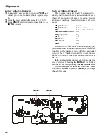
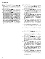
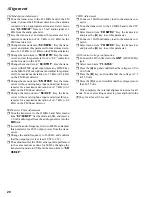
Power Amplifier Adjustment
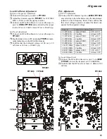
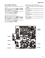
HF/50 MHz Idling Current Adjustment
r
Tune the transceiver to any HF band, or to the 50 MHz
band.
r
Disconnect the jumper between
TP3021
and
TP3022
.
r
Connect the ammeter between
TP3021
and
TP3022
.
r
Turn
VR3002
fully counterclockwise.
r
Press the PTT, and adjust
VR3002
for an indication
of 300 mA (±10 mA) on the ammeter.
r
Re-connect
TP3021
and
TP3022
.
V/UHF Idling Current Adjustment
r
Tune the transceiver to the 430 MHz band.
r
Connect the ammeter between
TP3021
and
TP3022
.
r
Connect the ammeter between
TP3021
and
TP3022
.
r
Turn
VR3001
fully counterclockwise.
r
Press the PTT, and adjust
VR3001
for an indication
of 300 mA (±10 mA) on the ammeter.
r
Re-connect
TP3021
and
TP3022
.
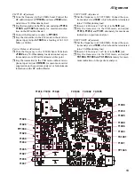
Directional Coupler Balance Adjustment
r
Terminate the antenna jack into a 50-Ohm dummy load.
Set the mode to CW, and connect the DC voltmeter to
TP3001
.
r
Tune the transceiver to the 28 MHz band, and key the
transceiver.
r
Adjust
TC3002
for minimum indication on the DC
voltmeter.
r
Tune the transceiver to 439.995 MHz, and key the trans-
ceiver.
r
Adjust
VR3003
for minimum indication on the DC
voltmeter.
r
Leave the transceiver on 439.995 MHz band and key
the transceiver.
r
Adjust
TC3001
for maximum indication on the RF
Power meter.
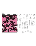
TP3021
TP3022
VR3003
VR3002
VR3001
TP3001
TC3002
TC3001
Содержание FT-897
Страница 5: ...Block Diagram 5...
Страница 6: ...Block Diagram 6 Note...
Страница 21: ...21 MAIN Unit Circuit Diagram...
Страница 22: ...22 MAIN Unit Note...
Страница 52: ...52 MAIN Unit Note...
Страница 59: ...59 PA Unit Circuit Diagram...
Страница 60: ...60 PA Unit Note...
Страница 73: ...73 PANEL Unit Circuit Diagram...
Страница 74: ...74 PANEL Unit Note...
Страница 75: ...75 PANEL Unit H Parts Layout Side A 1 2 3 F A C B E D BRPG1211C D4007 4010 4012 G...


