18
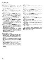
Over-current Protection Adjustment
r
Set the mode to CW. Select menu item “
18: HF1-IC
.”
Tune the transceiver to the 1.8 MHz band and key the
transceiver. Adjust this parameter for 140 Watts of
transmission power.
r
Select menu item “
19: HF2-IC
.” Tune the transceiver
to the 7 MHz band and key the trans-ceiver. Adjust
this parameter for 130 Watts of transmission power.
r
Select menu item “
20: HF3-IC
.” Tune the transceiver
to the 21 MHz band and key the transceiver. Adjust
this parameter for 130 Watts of transmission power.
r
Select menu item “
21: 50M-IC
.” Tune the transceiver
to the 50 MHz band and key the transceiver. Adjust
this parameter for 120 Watts of transmission power.
r
Select menu item “
22: VHF-IC
.” Tune the transceiver
to the 144 MHz band and key the transceiver. Adjust
this parameter for 60 Watts of transmission power.
r
Select menu item “
23: UHF-IC
.” Tune the transceiver
to 430.000 MHz and key the trans-ceiver. Adjust this
parameter for 25 Watts of transmission power.
Alignment
RF Power Adjustment
r
Tune the transceiver to the 1.8 MHz band in the CW
mode. Select menu item “
24: HF1-MAX
.” Key the
transmitter, and adjust this parameter for 100 Watts
(±5 W) of transmission power.
r
Select menu item “
25: HF1-MID2
.” Key the transmit-
ter, and confirm that the output power is 50 W (±5W).
In case the transmission power is not within the speci-
fied tolerance, adjust this parameter for 50 W (±5 W)
of transmission power.
r
Select menu item “
26: HF1-MID1
.” Key the transmit-
ter, and confirm that the output power is 10 W (±1 W).
In case the power is not within the specified tolerance,
adjust this parameter for 10 W (±1 W) of transmission
power.
r
Select menu item “
27: HF1-MIN
.” Key the transmit-
ter, and confirm that the output power is 5 W (±1 W).
In case the power is not within the specified tolerance,
adjust this parameter for 5 W (±1 W) of transmission
power.
r
The other RF power adjustment menus, [HF2-**] and
[HF3-**], should be adjusted in the same manner as
shown above for the 7 MHz and 21 MHz bands re-
spectively.
r
Tune the transceiver to the 50 MHz band in the CW
mode. Select menu item “
36: 50M-MAX
.” Key the
transmitter, and adjust this parameter for 100 W (±5
W) of transmission power.
r
Select menu item “
37: 50M-MID2
.” Key the trans-
mitter, and confirm that the output power is 50 W (±5
W). In case the transmission power is not within the
specified tolerance, adjust this parameter for 50 W (±5
W) of transmission power.
r
Select menu item “
38: 50M-MID1
.” Key the trans-
mitter, and confirm that the output power is 20 W (±
2W). In case the power is not within the specified tol-
erance, adjust this parameter for 20 W (±2 W) of trans-
mission power.
r
Select menu item “
39: 50M-MIN
.” Key the transmit-
ter, and confirm that the output power is 5 W (±1 W).
In case the power is not within the specified tolerance,
adjust this parameter for 5 W (±1 W) of transmission
power.
r
Tune the transceiver to the 144 MHz band in the CW
mode. Select menu item “
40: VHF-MAX
.” Key the
transmitter, and adjust this parameter for 50 W (±2.5
W) of transmission power.
r
Select menu item “
41: VHF-MID
.” Key the transmit-
ter, and confirm that the output power is 20 W (±2 W).
In case the transmission power is not within the speci-
fied tolerance, adjust this parameter for 20 W (±2 W)
of transmission power.
Содержание FT-897
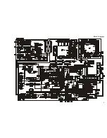
Страница 5: ...Block Diagram 5...
Страница 6: ...Block Diagram 6 Note...
Страница 21: ...21 MAIN Unit Circuit Diagram...
Страница 22: ...22 MAIN Unit Note...
Страница 52: ...52 MAIN Unit Note...
Страница 59: ...59 PA Unit Circuit Diagram...
Страница 60: ...60 PA Unit Note...
Страница 73: ...73 PANEL Unit Circuit Diagram...
Страница 74: ...74 PANEL Unit Note...
Страница 75: ...75 PANEL Unit H Parts Layout Side A 1 2 3 F A C B E D BRPG1211C D4007 4010 4012 G...

