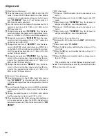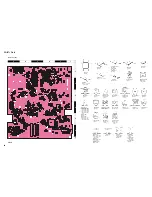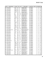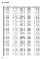
14
Alignment
RX Adjustment
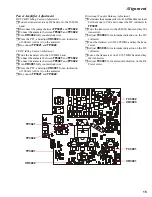
The PA Unit must be connected during RX adjustments.
The signal generator should not be connected to
J1003
directly because DC voltage is present there.
RX IF Adjustment
Connect the signal generator to the antenna connector,
and the SINAD meter to the speaker jack.
SSB IF Adjustment
r
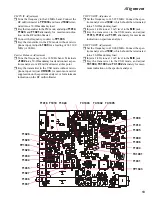
Tune the transceiver to 51.995 MHz. Inject an RF sig-
nal from a signal generator at 0 dBµ output.
r
Adjust
T1018
,
T1019
,
T1024
,
T1026
,
T1028
,
T1030
,
T1035
,
T1036
,
T1037
,
T1034
and
T1029
alternately for maximum indication on the DC volt-
meter. Several passes may be necessary, as the adjust-
ments inter-react to some degree.
FM IF Adjustment
r
Tune the transceiver to 51.995 MHz. Inject an RF sig-
nal from a signal generator at 5 dBµ output, with 1
kHz AF FM modulation at ±3.5 kHz deviation.
r
Adjust
T1024
,
T1026
, and
T1028
alternately for
maximum level on the S-meter.
Air-Band Reception Adjustment
r
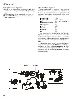
Connect the DC voltmeter to
TP1044
.
r
Tune the transceiver to 128.00 MHz in the AM mode.
Inject an RF signal from the signal generator at 20 dBµ
output, with 30% AM modulation at 400 Hz audio fre-
quency.
r
Adjust
T1005
and
T1008
for minimum indication on
the DC voltmeter.
VHF Band Alignment
r
Connect the DC voltmeter to
TP1044
.
r
Tune the transceiver to 145.995 MHz in the CW mode.
Inject an RF signal from a signal generator at 20 dBµ
output.
r
Adjust
T1006
,
T1009
and
T1010
alternately for mini-
mum indication on the DC voltmeter.
UHF Band Alignment
r
Connect the DC voltmeter to
TP1044
.
r
Tune the transceiver to 439.995 MHz in the CW mode.
Inject a RF signal from the signal generator at 20 dBµ
output.
r
Adjust
TC1001
for minimum indication on the DC
voltmeter.
W-FM Reception Adjustment
r
Connect the SINAD meter to the speaker jack.
r
Tune the transceiver to 88.00 MHz. Inject a RF signal
from the signal generator at 30dBu output, with ±22.5
kHz deviation FM modulation of a 1 kHz audio signal.
r
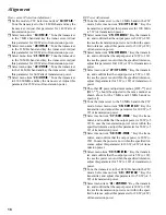
Adjust
TC1005
for the best SINAD sensitivity. Then
reduce the output level of the signal generator to where
the signal just begins to sound slightly “noisy,” and
adjust
TC1005
again for best SINAD.
Image Rejection Trap Adjustment
r
Connect the AF millivoltmeter to the speaker jack.
r
Tune the transceiver to 51.995 MHz in the FM mode.
Inject an RF signal from the signal generator at 68.330
MHz, with 70 dBµ output.
r
Adjust
T1004
for minimum indication on the AF
millivoltmeter. Then increase the output level of the
signal generator slightly and adjust
T1004
again, so
as to ensure maximum notching of the image.
Noise Blanker Adjustment
r
Connect the DC voltmeter to
TP1043
. Tune the trans-
ceiver to 51.995 MHz and inject an RF signal from the
signal generator at 20 dBµ output.
r
Activate the noise blanker, and adjust
T1027
and
T1031
for minimum indication on the DC voltmeter
connected to
TP1043
.
Содержание FT-897
Страница 5: ...Block Diagram 5...
Страница 6: ...Block Diagram 6 Note...
Страница 21: ...21 MAIN Unit Circuit Diagram...
Страница 22: ...22 MAIN Unit Note...
Страница 52: ...52 MAIN Unit Note...
Страница 59: ...59 PA Unit Circuit Diagram...
Страница 60: ...60 PA Unit Note...
Страница 73: ...73 PANEL Unit Circuit Diagram...
Страница 74: ...74 PANEL Unit Note...
Страница 75: ...75 PANEL Unit H Parts Layout Side A 1 2 3 F A C B E D BRPG1211C D4007 4010 4012 G...


