12
Alignment
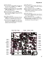
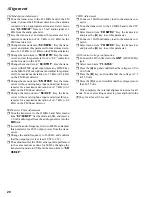
PLL Unlock
r
Connect the DC voltmeter to pin 1 of
J2002
(
TP1027
).
r
Disconnect the reference oscillator input by unplug-
ging the cable; confirm that the voltmeter shows less
than 0.5 V and that “
UNLOCK
” is displayed on the
LCD.
r
Re-connect the reference input, and confirm that the
voltmeter shows at least 3.5 V and tat the LCD returns
to its normal display.
Idling Current Adjustment
Before alignment, set the mode to CW and tune the
transceiver to 1.800 MHz. Nothing should be connected
to the CW Key Jack. Switch off
S1001
.
Pre-Driver Stage Idling Current
r
Connect the ammeter between
TP1019
and
TP1020
.
r
Press the PTT, and adjust
VR1004
for an indication
of 35 mA (±2 mA) on the ammeter.
Driver Stage Idling Current
r
Connect the ammeter between
TP1017
and
TP1018
.
r
Press the PTT and adjust
VR1003
for an indication of
30 mA (±2mA) on the ammeter.
Exciter Stage Idling Current
r
Terminate
J1004
into a ammeter.
r
Turn both
VR1001
and
VR1002
fully counterclock-
wise.
r
Press the PTT and adjust
VR1002
for an indication of
100mA (±10 mA) on the ammeter.
r
Press the PTT and adjust
VR1001
for an indication of
200mA (±10 mA) on the ammeter.
r
Re-connect
J1004
and switch on
S1001
.
TX IF Adjustment
SSB/CW TX IF Adjustment
r
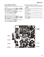
Tune the frequency to the 14 MHz band. Connect the
RF millivoltmeter to
TP1033
, and terminate
J1002
into a 50-Ohm dummy load.
r
Inject a 1 kHz tone at 1 mV level to the
MIC jack
.
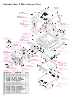
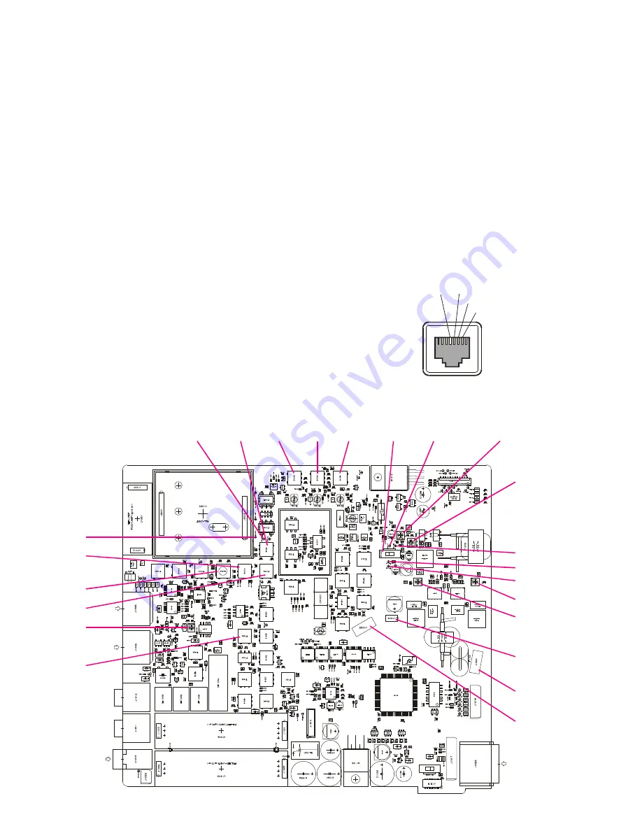
TP1027
S1001 TP1017
TP1018
TP1019
TP1020
VR1003
VR1004
VR1002
VR1001
J1004
TP1033
T1033
J1002
T1014
T1021
T1023
L1049
VR1005
T1013 T1012 T1011
J1003
r
Key the transmitter, and adjust
T1033
for maximum
indication on the RF millivoltmeter.
GND
PTT
MIC
MIC GND
Содержание FT-897
Страница 5: ...Block Diagram 5...
Страница 6: ...Block Diagram 6 Note...
Страница 21: ...21 MAIN Unit Circuit Diagram...
Страница 22: ...22 MAIN Unit Note...
Страница 52: ...52 MAIN Unit Note...
Страница 59: ...59 PA Unit Circuit Diagram...
Страница 60: ...60 PA Unit Note...
Страница 73: ...73 PANEL Unit Circuit Diagram...
Страница 74: ...74 PANEL Unit Note...
Страница 75: ...75 PANEL Unit H Parts Layout Side A 1 2 3 F A C B E D BRPG1211C D4007 4010 4012 G...


