


— 12 —
IV. Connection to Engine Network
Read and become fully familiar with the contents of this section. Never connect the Device
to the connector that ‘just looks right’ until you are sure about its wiring. If you have any doubts,
ask a specialist.
Modern engine networks may seem very complicated and may have many similar connectors with
different wiring and different purposes. Some engines, which only differ by one character in the
model name, may have a vastly different electronics and different wiring. Be sure that you are using
the appropriate manual. Usually, a manual lists the colors of wires, and you may check a connector
by the color of the incoming wires.
Never disconnect or connect any connectors when the circuit breaker is ON. The entire installation process
must be performed with no power coming into the engine network and with the engines disconnected
at the circuit breaker.
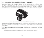
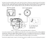
The Device uses two data lines called «CAN HIGH» and «CAN LOW», and two power supply lines:
VCC (positive) and GND (negative, ground), see Appendix E. We strongly recommend checking
the engine connector wiring in the engine’s manual, and verifying your engine connector wiring with
a simple multimeter to be sure that you find the right connector:
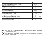
• turn OFF the circuit breaker and check resistance between the CAN HIGH and CAN LOW pins,
it must be 60 – 120 Ohm;
• turn on the circuit breaker (for some models ignition also should be on) and check voltage on the
VCC and GND pins (be careful not to short-circuit anything) of the connector, it must be 12 –24 V.
Содержание YDEG-04
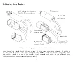
Страница 10: ...10 Figure 1 Device with MicroSD card pin side visible at left label side at right...
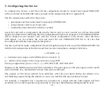
Страница 49: ...49 Figure 1 Raymarine c125 MFD devices list with Gateway YDEG 04...
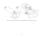
Страница 63: ...63 Appendix E Device Connectors Figure 1 NMEA 2000 connectors of the YDEG 04R left and YDEG 04N right models...