Installation
System 182-XT-4
3 - 38
ba76027e02
12/2014
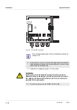
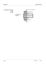
Fig. 3-30 24 V AC/DC connection.
WARNING
No free wires must be allowed to project into the enclosure.
Otherwise there is the danger of short circuits that can cause a
fire. Always cut off any wires that are not in use as closely as
possible to the cable gland.
The complete assignment of the terminal strip is shown in
section 3.12.
8
Connect wires 1 and 2 to the terminal strip. Make sure that the
cable assignment agrees with the specification on the terminal
label under the terminal strip.
9
Tighten the coupling ring (pos. 3 in Fig. 3-29).
10
Close the enclosure of the DIQ/S 182 XT-4-PR.
Terminal
labeling:
X17
X16
24V AC DC
INPUT
POWER
Содержание YSI 182-XT-4
Страница 6: ...Contents System 182 XT 4 0 4 ba76027e02 12 2014...
Страница 10: ...Overview System 182 XT 4 1 4 ba76027e02 12 2014...
Страница 14: ...Safety System 182 XT 4 2 4 ba76027e02 12 2014...
Страница 64: ...Installation System 182 XT 4 3 50 ba76027e02 12 2014...
Страница 82: ...Operation System 182 XT 4 4 18 ba76027e02 12 2014...
Страница 88: ...The SETTINGS menu System 182 XT 4 5 6 ba76027e02 12 2014...
Страница 114: ...Relay outputs System 182 XT 4 6 26 ba76027e02 12 2014...
Страница 116: ...Maintenance and cleaning System 182 XT 4 7 2 ba76027e02 12 2014...
Страница 122: ...What to do if System 182 XT 4 8 6 ba76027e02 12 2014...
Страница 134: ...Technical data System 182 XT 4 9 12 ba76027e02 12 2014...
Страница 135: ...System 182 XT 4 1 ba76027e02 12 2014...
Страница 138: ...Accessories and options System 182 XT 4 11 2 ba76027e02 12 2014...
Страница 142: ...Appendix store separately if required System 182 XT 4 13 2 ba76027e02 12 2014...
Страница 143: ......


