Page | 57
8.
Communications
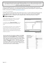
Ai1 products typically use an internal cellular modem or an Iridium SBD transceiver. Inside the housing is an
integrated 3dBi antenna suitable for the communications
method. If you are unsure of the model provided, connect
using USB and DevConfig. Under Deployment ->
Datalogger will be a tab referring to the Cellular
communications setup.
8.1
USB Radio Modem (RADUSB)
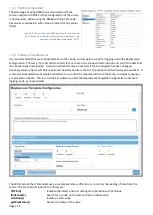
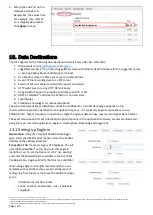
The RADUSB is a simple low power USB radio modem used for establishing
real-time communications with the Ai1. This radio provides the same
functionality as available through the local USB port of the Ai1. The RADUSB
shows the radio information including frequency (433/915MHz) and the
operation of the internal LED’s. The Green LED shows the status of the radio
link. When first powered up the LED will flash green indicating that it is
searching for a matching radio. When found, the LED will be always-on. If
the radio fails to pair, confirm the Ai1 has the radio on and is within range.
Model
Distance with 2dBi antenna Region
915MHz, 100mW
150 to 200m typically
USA, Australia, Asia
433MHz, 100mW
200 to 250m typically
Europe inc UK, Aus
18
.
To connect, use DevConfig. Find the COM port assigned to the radio by using the pull-down icon next to the
communications port. The baud rate must be set to 57,600 for the radio to connect. All subsequent operation is the
same as using a local USB cable connected to the Ai1.
8.2
Radio Base Station (RADOUT)
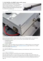
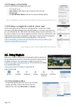
The RADOUT provides RS232 serial output of the information transmitted by the Ai1. The
internal radio has the same operating specifications as RADUSB (i.e., 433 or 915MHz) but
includes a higher gain antenna (3dBi) and is in a weatherproof enclosure designed for
pole mounting. The RADOUT includes two U-bolts suitable for poles from 38mm to
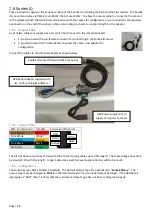
65mm in diameter. At the bottom of the radio is an M12 connector. The RADOUT
includes a matching 5m flying lead cable with the following wires:
Brown
+12V power supply (3-16V range, ~18mA @ 12V)
Black
Power and Signal Ground
White
RS232 TX (data from radio)
Blue
RS232 RX (data to radio). Optional, not required for receive only mode
The electrical interface is RS232 with fixed baud of 57,600, 8 data bits, no stop bits, 1
parity bit
19
. The protocol is similar to NMEA 0183
20
with the following structure:
$YYMMDD,HHmmSS,a.aa,b.bb,c.cc*CK{CR}{LF}
21
•
$
is the identifier for the start of the message.
•
YYMMDD
is the 6-digit date where
YY
is year,
MM
is month and
DD
is day
•
HHmmSS
is the 6-digit time where
HH
is the hour,
mm
is the minutes,
SS
is the seconds
•
a.aa
is the floating-point value for Parameter 1,
b.bb
is for Parameter 2, etc. The values that Parameter 1, 2,
3 and so on represent is custom programmed in the Ai1 for the project.
•
*
is the data terminator
•
CK
is a 2-byte XOR checksum of all bytes between the string identifier and data terminator, same as used by
NMEA 0183. The checksum is always 2-digits with a leading zero for values less than 10.
•
{CR}{LF}
are the
Carriage Return
(ASCII char 13) and
Line Feed
(ASCII char 10) indicating end of the message.
18
Australia permits 433MHz as Low Interference Potential Devices (LIPD): https://en.wikipedia.org/wiki/ISM_radio_band#Frequency_allocation
19
It is possible to order a UART (5V TTL) serial interface version, specify RADOUT-UART.
20
NMEA is as used by the GPS and of the same structure except the identifier includes a 5-character string message.
21
Date and time separators can be included by defining the program Const VERBOSE_OUT which results in YY/MM/DD and HH:mm:SS as the date & time format

