Page | 21
3.4.1
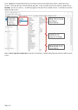
M12 Connector Assembly Notes
An instructional video is available showing all the
steps required to assemble the field wireable
connector kit. Visit
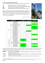
Pin numbering is embossed inside the connector
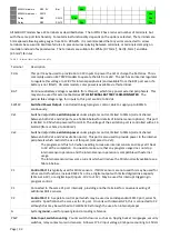
Potting M12 connector for waterproofing and reliability
When using field wireable connector, prepare the cable by stripping approximately 32mm of the outer insulation
and cut the wire connecting to pin 5 shorter by 7mm. Cut short any unused wires. Strip approximately 4mm of
insulation from each wire and bend exposed wire back on the insulation (see video above for visualization). Install
the wire in pin 5 first and tighten the screw firmly so it bites into the insulation. Repeat for remaining wires.
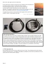
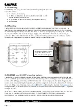
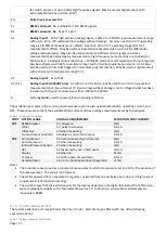
When assembling the backshell onto the connector, orientate the notch at 1:30 (when
the cable is pointing downward at 6:00). Tighten the plastic nut on the backshell. Use
the supplied two-part epoxy to eliminate any potential moisture build up and provide
additional mechanical strength
5
.
3.5
Universal Wiring System
The Ai1POLE has standardized the wiring for connecting many common environmental sensors. The default wiring
suits a wide range of sensors, SDI12, serial, analog and pulse, through a
5-pin female M12 connector
(IEC 61076-2-
101 connector). An optional 2
nd
M12 connector allows for more sensors to be added, using SDI12,
serial, analog and pulse ports. If the Ai1POLE is ordered with the RS485 option, the port is wired to suit
5
Uncured epoxy requires special handling through shipping and so are not included with the Ai1 materials. A wide variety of two-part epoxies are locally purchased (
), with
approximately 3g required per connector. The connector does include a gland and o-ring seal mechanism to provide waterproofing, but the epoxy provides additional strength.
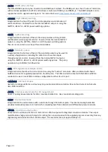
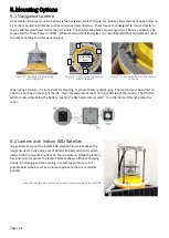
Figure 10 - Correct installation of the M12 connector, with a cable
loop pointing downwards to ensure rainfall drips off, and use of the
cable tie point for securing sensor cable

