29
Version 1 – GBR (25/10/2022)
D-502-0287
-
4.2.5.
Connection of the unit to the parent BMS system using the Modbus RTU protocol
-
Unit equipped with the possibility of connection to a higher-level BMS system (hereinafter referred to
as BMS).
-
The connection of the unit to the parent BMS must be carried out by a competent, knowledgeable
person.
-
The connection of the unit to the BMS must always be made using the “XCONT-HUB” accessory.
Addressed by the separate “XCONT-HUB” accessory manual
-
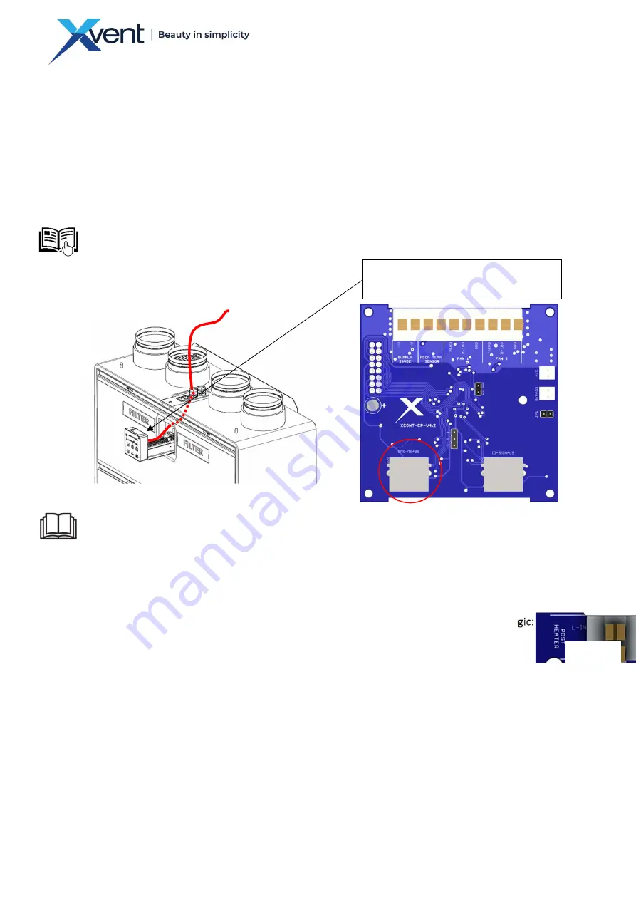
The connection cable (included in the “XCONT-HUB” package) between the controller and the ”XCONT-
HUB” accessory is connected to the controller, which is located in the lid of the unit.
-
Insert the connection cable into the controller according to chapter 4.2.1.
-
Plug the connection cable into the RJ connector marked BMS-RS485
-
Communication of the unit with the parent BMS system is solved by the Modbus RTU communication
protocol. Protocol description is addressed in the separate user manual “D-502-xxx-Vxxx-xxx-MN-
CENTRAL-MODBUS”
4.2.6.
Connecting an external electric heater - (POSTHEATER)
-
The unit can be connected to an external electric heater (hereinafter referred to as a heater) with the
maximum output of 1,500 W, voltage 1 x 230 V.
-
The unit switches only the supply phase - potential (L-IN) to the heater (L-OUT) in the logic:
o
If the unit is ventilating, the phase is switched - the potential is switched
o
If the unit is stationary, the switched phase - potential is open
o
If the unit is ventilating but the ventilation request is terminated (AQS control - automatic
regime).
The unit disconnects the switched phase
The power of the unit's fans is reduced to the minimum and the after-cooling regime
runs for 3 min
The after-cooling regime is indicated by a flashing LED on the controller above the
ON/OFF button
-
The unit's control cannot detect the presence of an external heater, so it assumes it is always
connected. The result is that whenever the fans are switched off (either by user request or AQS
sensors), the after-cooling function is triggered.
-
We recommend using a heater with a channel sensor (for temperature control) and control via an
external contact from the unit
Rear view of the controller - connector
connection for BMS control
Fig. 35
Fig. 36
Содержание XHOUSE-300
Страница 8: ...8 Version 1 GBR 25 10 2022 D 502 0287 5x 6 7 5 8 9 Fig 2 5 8 19 Fig 3...
Страница 9: ...9 Version 1 GBR 25 10 2022 D 502 0287 10 11 12 14 13 20 21 15 Fig 4 Fig 5...
Страница 31: ...31 Version 1 GBR 25 10 2022 D 502 0287 4 3 Block diagram of the Xhouse unit wiring Fig 38...
Страница 34: ...34 Version 1 GBR 25 10 2022 D 502 0287 5 4 2 Description of the functions of the buttons and regulation Tab 14...


