15
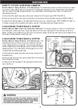
The cutting edges of the shredding hammers may eventually wear out requiring rotation of the hammer or
replacement if all cutting edges have been dulled. Triangular hammers can be rotated twice after the first
edge dulls, then flipped over once and rotated again for a total of 6 edges. J-hammers can be flipped over
once for a total of two cutting edges.
Shredding Hammer Rotation and Replacement
1.
Turn the engine off and wait for all moving parts to stop.
2.
Disconnect the spark plug wire and secure it away from the spark plug. SEE FIGURE 12
3.
Detach the rotor housing and hopper from the rotor plate. SEE FIGURE 13
4.
Note the assembly sequence of the hardware used to secure the hammers. Using an 8mm allen wrench
remove the socket head cap screw (A) and related hardware. SEE FIGURE 14
5.
Inspect the hammers (C, G), spacer tubes (D, E), and hardware. If the spacer tube (D, E) shows signs of
wear, replace it. Inspect and flip, or replace the hammers (G, C).
6.
Reassemble the hammers, spacers, washers, and cap screws. Torque the socket head cap screws (A) to
30-35 ft. lbs. (41-47 N.m.) The J-hammer (G) on the opposite side of the rotor faces outward for balanced
rotation.
7
. Repeat for all the hammers.
To rotate the shredding hammers:
The chipping knives should be sharpened or replaced when tree limbs require extra force to feed into the
chipper cone. The chipping knives may be sharpened at a 30 degree angle until the distance between the
edge of the blade bevel and the mounting hole is less than 1/16” (1.6mm). SEE FIGURE 15.
Chipping Knives Sharpening and Replacement
1.
Turn the engine off and wait for all moving parts to stop.
2.
Disconnect the spark plug wire and secure it away from the spark plug. SEE FIGURE 12 (page 16)
3
. Detach the rotor housing and hopper from the rotor plate. SEE FIGURE 13
4.
Remove the rotor by removing the hardware that secures it to the engine crank shaft. SEE FIGURE 15
NOTE
: Do not lose spacer. During reassembly Be sure to place spacer is installed inside rotor. Without
spacer, rotor will interfere with housing components.
5.
Using a hex wrench, remove the two socket head cap screws and the chipper knife. SEE FIGURE 16
6.
Inspect, rotate, sharpen, or replace the chipper knife. SEE FIGURE 17
7.
Reinstall the chipper knife and tighten the socket head cap screws to 18-20 ft-lb (24-27 N.m.). We
recommend the use of high strength threadlocker on screws.
REPAIR
Содержание 212 CC
Страница 15: ...14 TROUBLESHOOTING ...
Страница 17: ...16 REPAIR ...
Страница 18: ...17 PARTS LIST ...
Страница 19: ...18 PARTS LIST ...
Страница 20: ...19 PARTS LIST ...
Страница 21: ...20 PARTS LIST ...
Страница 22: ...21 PARTS LIST ...
Страница 23: ...22 PARTS LIST ...


