


Xtreme Power Conversion Corporation
E90 Service Manual
Page 43
Uninterruptible Power Supply
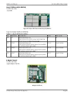
Replace DSP board
1. Ensure the safe conditions before any operation. Please read chapter 2 “Security conditions” and chapter 3
“shutdown-disassembly/reassembly UPS” carefully.
2. Operate according to the steps 1-3 of process A or steps 1-3 of process B in chapter 3;
3. Remove the screws of left panel of UPS, remove the cover, use the bleeder resistor to release the energy stored
in the Bus capacitor;
4. Remove all the cables of the DSP board;
5. Remove all the screws of the DSP board;
6. Replace the PCB, package the old PCB;
7. Install the screws and cables;
8. install the right panel and screws;
9. Continue with the steps 4-9 in process A or 4-8 in process B in chapter 3;
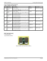
Replace PFC inductor board
1. Ensure the safe conditions before any operation. Please read chapter 2 “Security conditions” and chapter 3
“shutdown-disassembly/reassembly UPS” carefully.
2. Operate according to the steps 1-3 of process A or steps 1-3 of process B in chapter 3;
3. Remove the screws of left panel of UPS, remove the cover, use the bleeder resistor to release the energy stored
in the Bus capacitor;
4. Remove all the cables of the PFC inductor board;
5. Remove all the nuts and screws of the PFC inductor board;
6. Replace the PCB, package the old PCB;
7. Install the nuts, screws and cables;
8. install the left panel and screws;
9. Continue with the steps 4-9 in process A or 4-8 in process B in chapter 3;
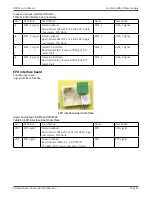
Replace PFC power board
1. Ensure the safe conditions before any operation. Please read chapter 2 “Security conditions” and chapter 3
“shutdown-disassembly/reassembly UPS” carefully.
2. Operate according to the steps 1-3 of process A or steps 1-3 of process B in chapter 3;
3. Remove the screws of left panel of UPS, remove the cover, use the bleeder resistor to release the energy stored
in the Bus capacitor;
4. Remove all the cables of the PFC power board
5. Remove all the screws of the PFC power board;
6. Replace the PCB, package the old PCB;
7. Install the screws and cables;
8. install the right panel and screws;
9. Continue with the steps 4-9 in process A or 4-8 in process B in chapter 3;
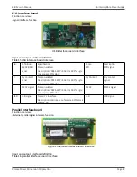
Replace INV inductor board
1. Ensure the safe conditions before any operation. Please read chapter 2 “Security conditions” and chapter 3
“shutdown-disassembly/reassembly UPS” carefully.
2. Operate according to the steps 1-3 of process A or steps 1-3 of process B in chapter 3;
3. Remove the screws of left panel of UPS, remove the cover, use the bleeder resistor to release the energy stored
in the Bus capacitor;
4. Remove all the cables of the INV inductor board
5. Remove all the screws and nuts of the INV inductor board;
6. Replace the PCB, package the old PCB;
7. Install the nuts, screws and cables;
8. install the left panel and screws;
9. Continue with the steps 4-9 in process A or 4-8 in process B in chapter 3;