


Xtreme Power Conversion Corporation
E90 Service Manual
Page 25
Uninterruptible Power Supply
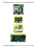
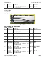
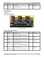
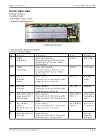
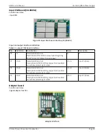
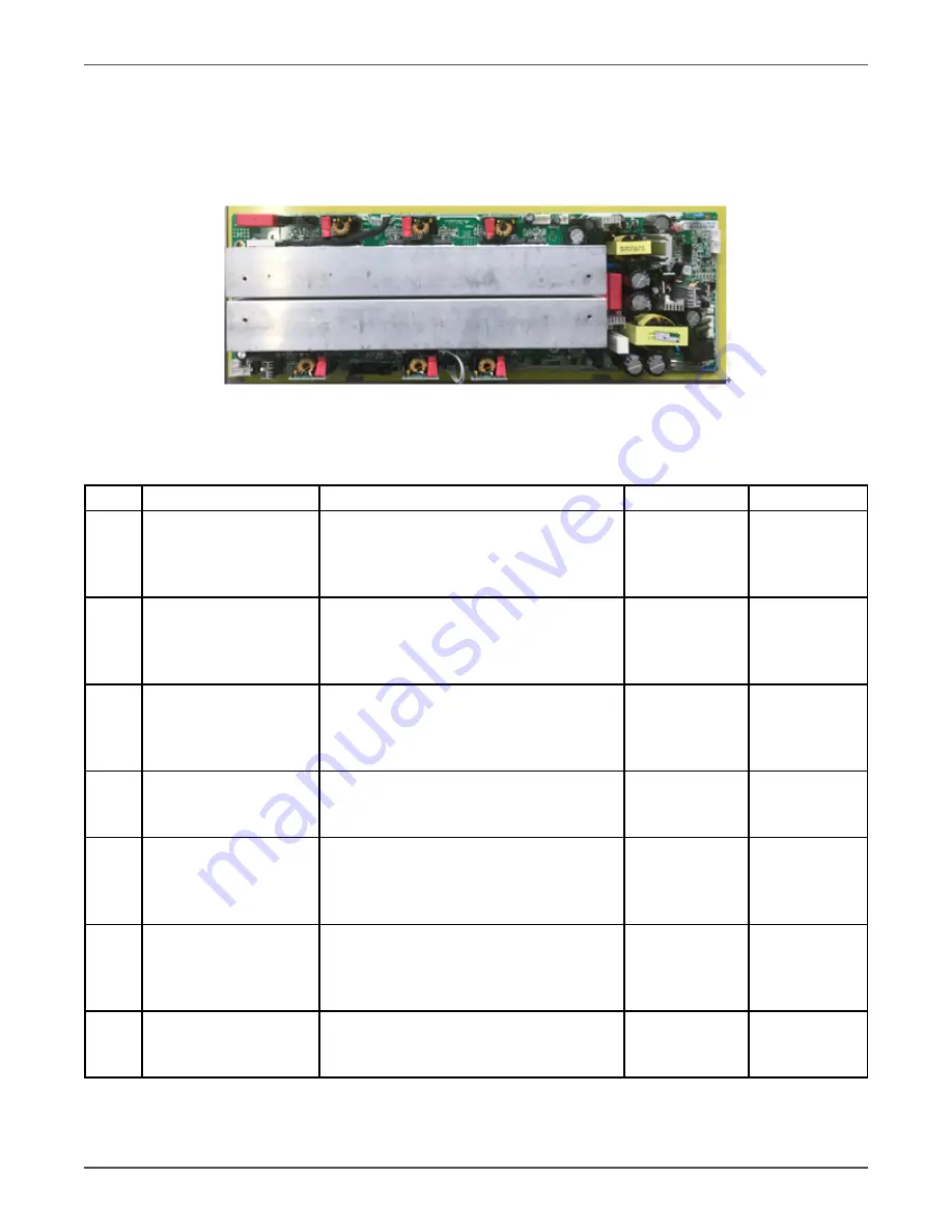
Inverter power board
Function overview:
-Auxiliary power
-Half-bridge inverter circuit
-Fan speed regulation circuit
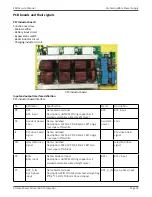
Inverter power board
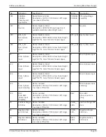
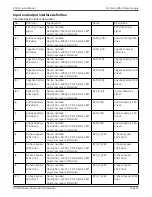
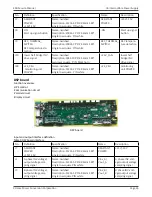
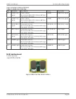
Input and output interface definition
Inv. Power board interface
No.
Definition
Specification
Name
Description
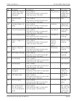
P9
+DCBUS
+BUS voltage
Name: blade terminal
Description: 4PIN 10A M4 screw hole
straight leg 8*8.4*11.1mm T0.8mm
tinned copper
+DCBUS
+BUS voltage
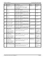
P10
-DCBUS
-BUS voltage
Name: blade terminal
Description: 4PIN 10A M4 screw hole
straight leg 8*8.4*11.1mm T0.8mm
tinned copper
-DCBUS
-BUS voltage
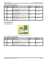
P13
15V/-15V
ASSISTANT
POWER
Name: neilsbed
Description: 1121S-2P P=3.96mm 180°
single row square PIN white
+15V/-15V
ASSISTANT
POWER
P28
+24V_FAN
Fan power
Name: neilsbed
Description: 1121S-2P P=3.96mm 180°
single row square PIN white
+24V_FAN
Fan power
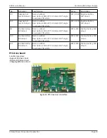
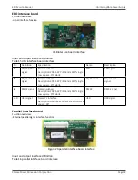
J4
VBPS_A/BAT+/VINV_A
Supply power from
auxiliary power
Name: neilsbed
Description: 1121S-5P P=3.96mm 180°
single row square PIN white (remove 2
4PIN)
VBPS_A/BAT+/
VINV_A
Supply power
from auxiliary
power
J5
REC_THERMAL_
SWITCH
REC temperature de-
tection
Name:neilsbed
Description:2001S-2P P=2.54mm 180°
single row square PIN white
REC_THERMAL_
SWITCH
REC tempera-
ture detection
J6
upper half bridge INV
drive signal
Name:neilsbed
Description:301S-12P P=2.54mm 180°
two rows square PIN black horn
upper half
bridge INV
drive signal