


Xtreme Power Conversion Corporation
E90 Service Manual
Page 18
Uninterruptible Power Supply
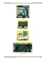
PCB boards and their signals
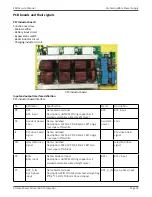
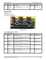
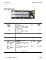
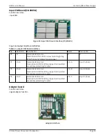
PFC inductor board
Function overview
- Mains rectifier
- Battery input circuit
- Bypass static switch
- Boost inductor circuit
- Charging inductor circuit
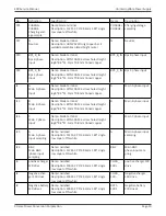
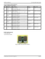
PFC inductor board
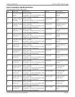
Input and output interface definition
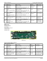
PFC inductor board interface
No.
Definition
Specification
Name
Description
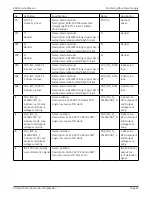
P8
BAT-
BAT- input
Name:blade terminal
Description: UHTWSZ Wiring copper bar II
welded assemblies plated bright nickel
BAT-
BAT- input
P6
Assistant power
15V+
Name: neilsbed
Description: 1121S-2P P=3.96mm 180° single
row square PIN white
Assistant
power
15V+
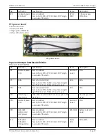
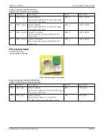
J1
PFC drive board
signal
Name: neilsbed
Description: 1121S-6P P=3.96mm 180° single
row square PIN white
PFC drive board
signal
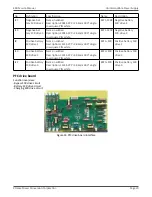
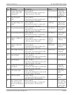
P15
relay/SCR drive
signal
Name: neilsbed
Description: 301S-10P P=2.54mm 180° two
rows square PIN black
relay/SCR drive
signal
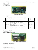
P5
BAT+
BAT+ input
Name: blade terminal
Description: UHTWSZ Wiring copper bar II
welded assemblies plated bright nickel
BAT+
BAT+ input
P7
BPS_A_IN
Bps A phase
input
Name:blade terminal
Description:4PIN 10A M4screw hole straight leg
8*8.4*11.1mm T0.8mm tinned copper
BPS_A_IN Bps A phase input