Service & Repair Manual
17
Copyright ©2015 XS Scuba
First Stage Reassembly
WARNING
: DO NOT attempt to use any other manufacturer's
part as a substitute for any XS Scuba part, regardless of
any similarity in shape, size, or appearance. Doing so may
render the product unsafe, and could result in serious injury
or death.
1. Lubricate and install the small dynamic O-ring(19) into the
first stage body(18), checking to ensure that it is seated properly
inside the groove.
2. Install the large external O-ring(15) onto the groove near the
end of the body.
3. Generously lubricate and install the large dynamic O-ring(23)
onto the head of the piston(22), and stand the piston on its
head.
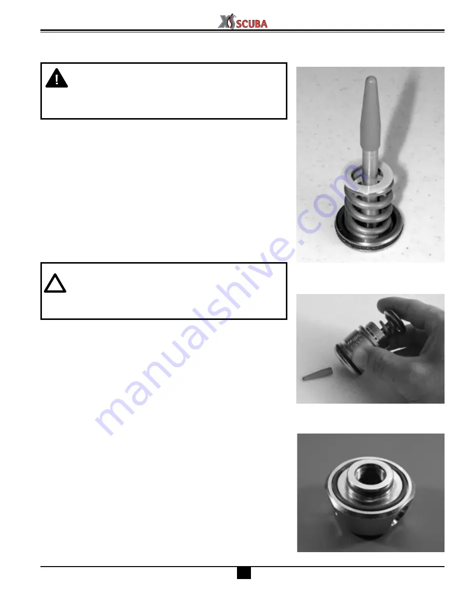
4. Apply a light film of lubricant to both ends of the high pressure
spring(21), and place the spring over the shaft of the piston.
5. Lay the spring washer(20) over the top of the spring.
NOTE
: If more than one washer was removed during disas-
sembly, be sure to reassemble the first stage using the same
number of washers, unless the HP spring has been discarded
and replaced with new. Up to three washers may be used.
▼
If one is needed, install between the spring and body.
▼
If two are needed, install on opposite sides of spring.
▼
If three are needed, install one between the spring and body,
and two between the spring and piston.
6. Insert a piston installation bullet into the end of the piston shaft.
This will protect the small dynamic O-ring inside the body, and
also the polished sealing surface of the piston (see Fig. 15).
7. Gently lower the threaded end of the body over the piston shaft,
until the body is supported by the spring . While holding the
piston and body together, turn the body over to allow the piston
installation bullet to drop out of the opposite end, tapping it
loose if necessary (see Fig. 16). Stand the body on end, with the
piston head facing up.
8. Lubricate and install the large O-ring(28) into the groove of the
swivel cap(30), and the smaller dynamic O-ring(28) onto the
swivel stem. (See Fig. 17.)
9. Mate the smaller end of the piston cap(25) over the stem of the
swivel cap, and press it downward so that it snaps securely into
place.
Fig. 15 – Piston w/ Installation Bullet
Fig. 17 – Swivel Retainer w/ O-rings
Fig. 16 – Removal of Bullet
Содержание SEAAIR
Страница 1: ...Service Repair Manual SERVICE AND REPAIR MANUAL SEAAIR REGULATOR PN RG200 Revised 02 11...
Страница 30: ......
Страница 31: ......


