


PIXIE-4 User’s Manual
V2.69
©
XIA
2015. All rights reserved.
xxviii
and the CFD time. For example, if the value is 0x0509, the CFD time is 5 + 9/256 ADC
sample steps away from the beginning of the recorded trace.
The User PSA value contains flags to indicate special events if it is not overwritten by
User DSP code. (CHAN_USERPSA bits 3|2|1|0 = Gate | Pileup | Out of range | Veto).
Normally, events that are piled up etc are rejected from the acquisition and do not
appear in the list mode data. However, when the advanced options to allow pileup or
out of range are enabled or when a VETO or GATE signal is present but rejection is
not enabled, such events are recorded. The data in User_PSA can be used to find such
events and treat them in special ways.
2.
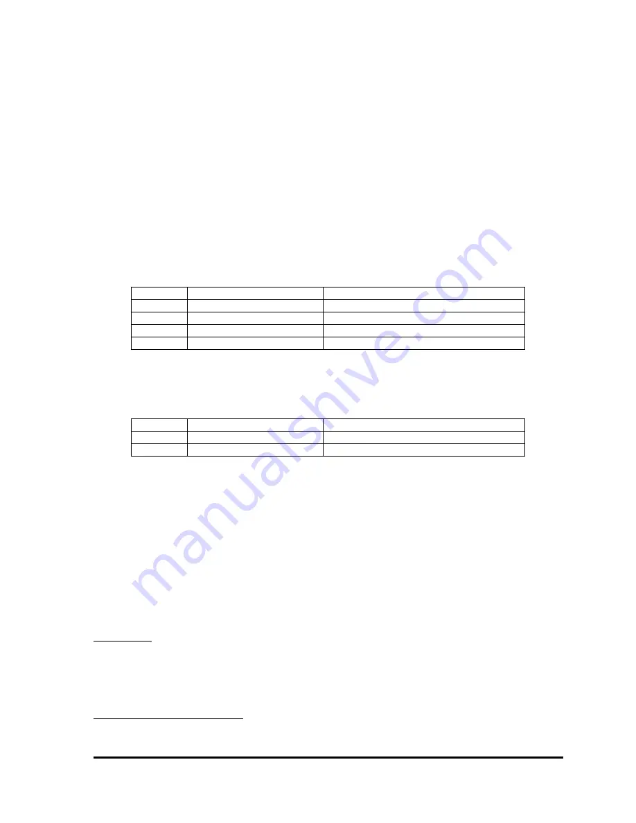
For compression 2 List Mode (RUNTASK = 258), CHANHEADLEN=4, and the four
words are:
Table 4.6: Channel header for compression 2 format.
Word #
Variable
Description
1
CHAN_TRIGTIME
Fast trigger time
2
CHAN_ENERGY
Energy
3
CHAN_XIAPSA
XIA PSA value
4
CHAN_USERPSA
User PSA value
3.
For compression 3 List Mode (RUNTASK = 259), CHANHEADLEN=2, and the two
words are:
Table 4.7: Channel header for compression 3 format.
Word #
Variable
Description
1
CHAN_TRIGTIME
Fast trigger time
2
CHAN_ENERGY
Energy
4.2.3 Reconstruction of list mode time stamps
As discussed above, in list mode the Pixie-4 records time information in three different
locations: The buffer header, the event header and the channel header. Below we describe how
to combine these time stamps into full timing information.
In the Pixie-4, there is a 48-bit time counter that is reset to zero at boot time or at a run start
with the “synchronize clocks” option selected. It is incremented at the full processor clock rate
of 75 MHz; the unit of the LSB is one 13.33ns
5
. Hence, the 48-bit word can span a time interval
of 43.44 days before rolling over.
At the beginning of a data acquisition run, the module looks at the counter and records the
BufferTime as a 48-bit number, using three 16-bit words. These three words are the time stamps
in the buffer header (BUF_TIMEHI, BUF_TIMEMI, BUF_TIMELO). Every time an event is
recognized, the DSP records the lower 32-bit of the time counter as two 16-bit words in the
event header (EVT_TIMEHI, EVT_TIMELO). Every time a channel triggers at the rising edge
of a pulse, the channel records the lowest 16 bit of the time counter, which is reported in the
5
For best precision, use 1us/75 in the conversion from clock ticks to seconds, 13.33e-9s may lead to rounding
errors.