background image

32

 |    

RAZORWELD™ 205SS MIG/TIG/STICK Welder Manual

TIG WELDING GUIDE

no pulse

high frequency 
pulsing

no pulse

high frequency 
pulsing

DC Pulse TIG Welding

Pulse TIG welding is when the current output (amperage) changes between high and low current.

Electronics within the welding machine create the pulse cycle. Welding is done during the high-amperage interval 

(this high amperage is referred to as peak current).  During the low amperage period, the arc is maintained but 

the current output of the arc is reduced (this low amperage is referred to as base current).  During pulse welding 

the weld pool cools during the low amperage period. This allows a lower overall heat input into the base metal. It 

allows for controlled heating and cooling periods during welding providing better control of heat input, weld pene

-

tration, operator control and weld appearance.


There are 4 variables within the pulse cycle: 
Peak Current  - Base Current - Pulse Frequency - Pulse Width
Setting and manipulation of these variables will determine the nature of the weld current output and is at the dis-
cretion of the operator. 

Peak Current

 is the main welding current (amps) set to melt the material being welded and 

works much the same 

as setting maximum amperage values for regular DC TIG: as a guide use 30-40 amps for every 1mm of material 

thickness.
Base Current

 is the set level of background current (amps) which cools the weld puddle and affects overall heat 

input. Background Amps is a percentage of peak amperage. As a rule, use enough background current to reduce 

the weld pool to about half its normal size while still keeping the weld pool fluid. As a guide start by setting the 

background amperage at 20 to 30 percent of peak amperage.
Pulse Frequency

 is the control of the amount of times per second (Hz) that the welding current switches from 

Peak Current to Base Current. DC Pulse TIG frequency generally ranges from 20 to 300 HZ depending on the job 
application.  Control of the pulse frequency also determines the appearance of the weld.
Pulse Width is the control of the percentage of time during one pulsing cycle the power source spends at the 

peak current (main amperage). Example is with the Pulse Width set at 80 percent and a rate of 1 pulse per sec

-

ond (PPS), the machine will spend 80% of the pulse at peak amperage and 20% at the base current. Increasing 

the pulse width percentage adds more heat to the job, while decreasing pulse width percentage reduces heat
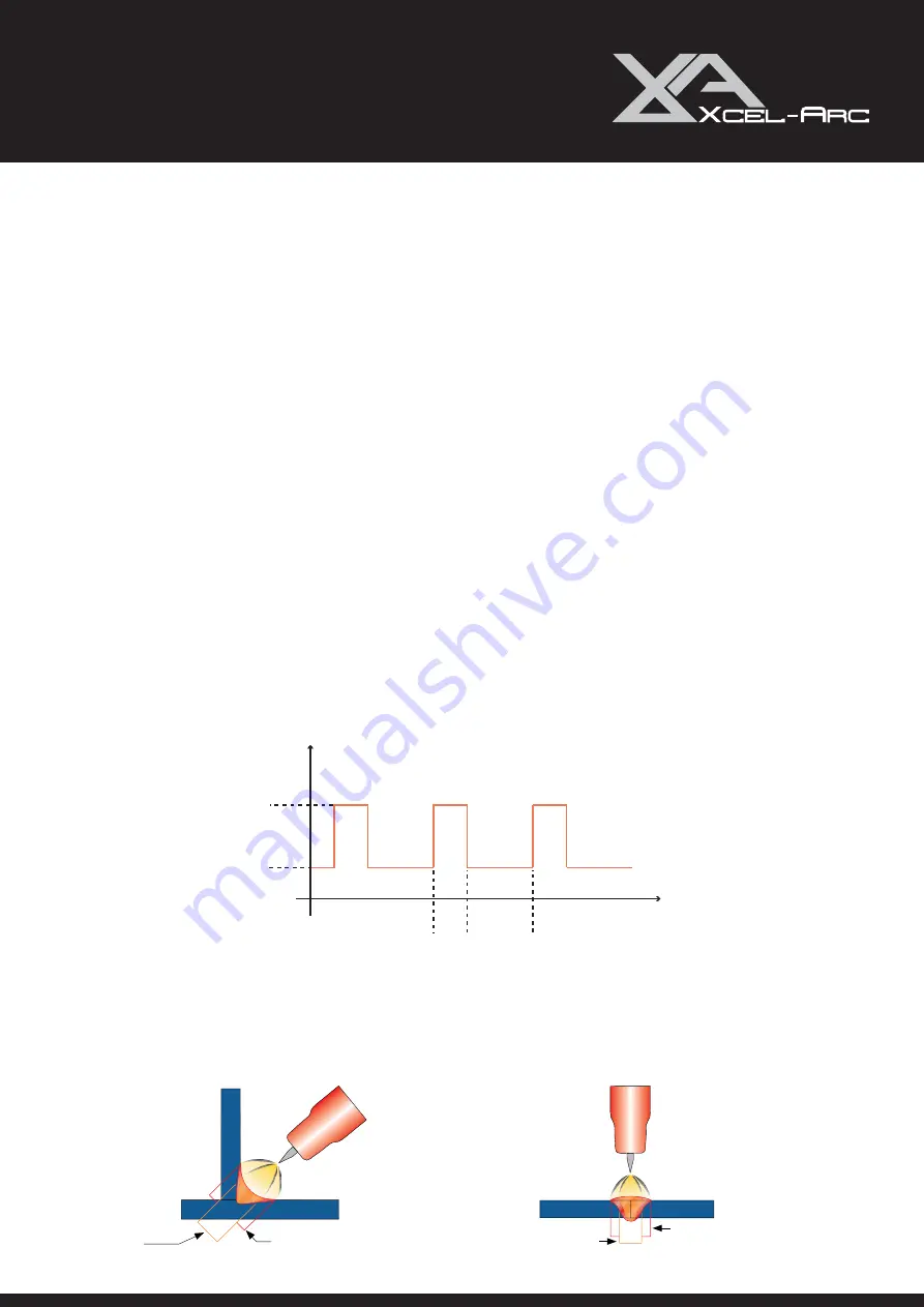
peak

background

ON

OFF

Current

Time

DC Pulse Tig welding allows faster welding speeds with better control of the heat input to the job, reducing the 

heat input minimising distortion and warping of the work and is of particular advantage in the welding of thin stain-
less steel and carbon steel applications. The high pulse frequency capability of the advanced inverter agitates the 
weld puddle and allows you to move quickly without transferring too much heat to the surrounding metal. Pulsing 

also constricts and focuses the arc thus increasing arc stability, penetration and travel speeds. 

Содержание RAZORWELD 205

Страница 1: ...this instruction manual carefully before the installation and operation of this equipment Xcel Arc 2021 RAZORWELD 205 SMART SET MIG TIG STICK WELDER Operating Manual XA MIG205SS 1 1 YEAR MACHINE WARR...

Страница 2: ...repair agent as appointed by this company Warranty does not cover abuse misuse accident theft general wear and tear New product will not be supplied unless ESSETI New Zealand Limited has inspected pr...

Страница 3: ...SET UP MIG 13 WIRE INSTALLATION AND 16 SET UP GUIDE 16 MIG WELDING GUIDE 21 INSTALLATION SET UP OF THE SPOOL GUN 27 INSTALLATION SET UP FOR DC TIG WELDING 29 TIG WELDING GUIDE 31 XA24 MIG TORCH SPARE...

Страница 4: ...for wear and tear replace the cable immediately if damaged bare wiring is dangerous and can kill Do not use damaged under sized or badly joined cables Do not drape cables over your body We recommend...

Страница 5: ...ers are normally part of the welding cutting process be sure to treat them carefully CYLINDERS can explode if damaged Protect gas cylinders from excessive heat mechanical shocks physical damage slag o...

Страница 6: ...ease refer to Main parameter table This equipment is of automatic voltage compensation which enables the maintaining of the voltage range within the given range In case that the voltage of input power...

Страница 7: ...on of the XASP24 Spoolgun for use with soft or very thin wires that often don t have the column strength to successfully feed through standard Mig Torches such as aluminium wire The Lift Arc DC TIG fu...

Страница 8: ...terminal 7 Euro Mig TIG Torch Connector 8 Output terminal 9 Weld Power Lead 10 2T 4T Selector Switch 7 11 MIG TIG MMA SMART SET Selector Knob 12 SpoolGun Power Supply Connection 1 2 10 BACK PANEL LAY...

Страница 9: ...rage Set 4 Down Slope Time Set 5 TIG Function Select 6 2T 4T Trigger Select ON OFF 4 5 6 3 2 1 MIG Function Front Panel Description 1 Voltage Display 2 Wire Feed Amperage Display 3 Wire Speed Set 4 Vo...

Страница 10: ...2 Connect the electrode lead to 1 Set MIG MMA selector switch to MMA 2 Connect the earth lead to 1 Turn the power source on and select the MMA function with the Tig MMA Mig selector switch 2 Connectio...

Страница 11: ...lted electrode metal is transferred across the arc into the molten pool and becomes the deposited weld metal The deposit is covered and protected by a slag which comes from the electrode coating The a...

Страница 12: ...lds General rule of thumb for down hand welding is to have an arc length no greater than the diameter of the core wire Electrode Angle The angle that the electrode makes with the work is important to...

Страница 13: ...line to the machine via the quick push lock connector located on the rear panel Check for Leaks 7 Place the Wire Spool onto the Spool Holder Snip the wire from the spool being sure to hold the wire t...

Страница 14: ...17 Select the wire feed speed required to suit the material thickness being welded it will show on the digital meter as m min Increasing the wire feed speed increases the welding amperage output Smar...

Страница 15: ...therefore more difficult to feed Soft wires can easily buckle at the wire feeder where the wire is fed into inlet guide tube of the torch The U shaped roller offers more surface area grip and tractio...

Страница 16: ...then loosen the outlet guide tube retaining nut too make adjustment if required Carefully retighten the locking nut and screw to hold the new position 4 Snip the wire carefully be sure to hold the wi...

Страница 17: ...ly remove the liner 4 Carefully unravel the new liner 8 Replace the front end parts 5 Carefully feed in the new liner down the torch lead all the way to exit the torch neck 9 Fully screw down the line...

Страница 18: ...ue to excessive wear By contrast larger diameter welding wires 1 2mm through 2 4mm have much higher columnar strength but it is important to make sure the liner has enough internal diameter clearance...

Страница 19: ...ner retaining nut together with the liner o ring 8 Push the liner firmly into the torch lead and tighten the liner retaining nut 9 Install a U groove drive roller of the correct size to match the wire...

Страница 20: ...nd over the drive roller 14 Tighten the torch euro connection to the machine euro connector 15 Cut the extended liner with a sharp Stanley knife just in front of the drive roller 16 Fit an Aluminium c...

Страница 21: ...t current power source is most commonly used with MIG welding There are four primary methods of metal transfer in MIG welding called short circuit also known as dip transfer globular transfer spray tr...

Страница 22: ...and the heat and force of the arc flattens out the droplet into the weld pool The heat of the arc melts the end of the wire slightly as it feeds towards the base metal The wire feed speed overcomes t...

Страница 23: ...technique directs the heat away from the weld puddle allowing faster travel speeds providing a flatter weld profile with light penetration useful for welding thin materials The welds are wider and fl...

Страница 24: ...avel angle of 5 15 is ideal and produces a good level of control over the weld pool A travel angle greater that 20 will give an unstable arc condition with poor weld metal transfer less penetration hi...

Страница 25: ...mm than is required resulting in a weld deposit of poor quality Travel Speed Travel speed is the rate that the gun is moved along the weld joint and is usually measured in mm per minute Travel speeds...

Страница 26: ...e weld produced would contain defects like porosity lack of fusion and slag inclusions Additionally some of the gas becomes ionised electrically charged and helps the current flow smoothly The correct...

Страница 27: ...connector located on the rear panel 9 Take the Spool Gun and remove the spool cover 10 Place the Wire Spool onto the Spool Holder Hold and snip the wire from the spool being sure to hold the wire to...

Страница 28: ...the gas cylinder valve and set the flow rate to between 8 12 l min 18 Select MIG function and 2 or 4T Trigger function on the front panel 19 Set the welding parameters using the wire feed and voltage...

Страница 29: ...rate for 12 l min 7 Select TIG functionon the front panel Set torch operation 2T 4T When 2T operation is selected press trigger Gas starts touch and lift arc start release trigger Gas and Arc stops Wh...

Страница 30: ...e of tungsten electrode for the job the tungsten electrode requires a sharpened point for DC welding 10 Lay the outside edge of the Gas Cup on the work piece with the Tungsten Electrode 1 2mm from the...

Страница 31: ...ls into a weld pool TIG welding offers the user the greatest amount of flexibility to weld the widest range of material and thickness and types DC TIG welding is also the cleanest weld with no sparks...

Страница 32: ...overall heat input Background Amps is a percentage of peak amperage As a rule use enough background current to reduce the weld pool to about half its normal size while still keeping the weld pool flui...

Страница 33: ...ng the weld pool 75 15 Form a weld pool Travel direction Angle torch Add Tig filler wire Retract the filler wire Move the torch forward to the front of the weld pool Repeat the process gas shield TIG...

Страница 34: ...superior arc starting electrode lifetime and overall cost effectivenes When E3 Tungsten Electrodes are compared with 2 thoriated tungsten E3 requires fewer re grinds and provides a longer overall life...

Страница 35: ...ture of the grain running lengthwise and thus grinding crosswise is grinding against the grain If electrodes are ground crosswise the electrons have to jump across the grinding marks and the arc can s...

Страница 36: ...rflex Cable Assembly x 5m 7 XA2514 Ergo Handle Kit c w Lock Nut 8 XA2516 Medium Large Ergo Trigger 9 XA2517 Hanger Hook optional extra 10 XA2841 Cable Support 11 XA1522 Cable Terminal Male 12 XA1505 L...

Страница 37: ...XA2513 30B Teflon Liner 1 0 1 2mm x 3 4m for Soft wire Red XA2513 40B Teflon Liner 1 0 1 2mm x 4 4m for Soft wire Red XA2513 50B Teflon Liner 1 0 1 2mm x 5 4m for Soft wire Red XA2564 30 PA Liner 1 0...

Страница 38: ...lar Cold Press Terminal 20 XA1521 Cable Terminal 21 XAPMS1 Motor Screw Pack Spare Parts Part Number Description 22 P7020 24 4 Screw 23 XAP7020W 08U Driver Roll For Aluminium Wire 0 8 XAP7020W 09U Driv...

Страница 39: ...A Contact Tip ECu 1 0Amm D8 M6 x 28mm for Aluminium XA2504 12A Contact Tip ECu 1 2Amm D8 M6 x 28mm for Aluminium XA2504 16A Contact Tip ECu 1 6Amm D8 M6 x 28mm for Aluminium 26 0 M6 x 1 0 M6 x 1 0 19...

Страница 40: ...rts Part Number Description 1 XA26 Torch Body Standard XA26FX Torch Body Flexible 2 57Y02 Back Cap Long 2a 98W18 Back Cap O Ring 3 57Y05 Back Cap Medium 4 57Y04 Back Cap Short 5 ER1MS Momentary Switch...

Страница 41: ...ens Front End Parts 18CG Cup Gasket 54N01 Gas Lens Gasket USTB80300236 Gas Lens Gasket 10N22S Stubby Collet 1 0mm 10N23S Stubby Collet 1 6mm 10N24S Stubby Collet 2 4mm 10N25S Stubby Collet 3 2mm USTB4...

Страница 42: ...ng in fusion defects also porosity and embrittlement of the weld metal Selecting the right type of shielding gas depends on the welding process being used and type of material being welded The MIG pro...

Страница 43: ...se the amperage or choose a larger electrode Poor welding technique Use the correct welding technique or seek assistance for the correct technique Poor joint preparation Check the joint design and fit...

Страница 44: ...rease etc Gas nozzle clogged with spatter worn or out of shape Clean or replace the gas nozzle Missing or damaged gas diffuser Replace the gas diffuser 3 Wire stubbing during welding Possible Reason S...

Страница 45: ...feeding Try to clear the liner by blowing out with compressed air as a temporary cure it is recommended to replace the liner Wrong size liner Install the correct size liner Blocked or worn inlet guid...

Страница 46: ...heck hoses and fittings for holes leaks etc Moisture on the base metal Remove all moisture from base metal before welding Contaminated base metal Remove materials like paint grease oil and dirt includ...

Страница 47: ...lding Incorrect tungsten size and or tung sten being used Check and change the size and or the tungsten if required Excessive rectification in the base metal Increase balance control Increase travel s...

Страница 48: ...ing Warranty Periods effective from the date of purchase XCEL ARC Inverter MIG SWF MTS MMA TIG TIG ACDC Plasma Power Source Only 2 Years RAZORWELD Inverter MIG SWF MTS MMA TIG TIG ACDC Power Source On...

Страница 49: ...re also entitled to at the consumer s discretion either a refund of the purchase price of the goods or repair of the goods or replacement of the goods Returns will only be accepted provided that a You...

Страница 50: ...Welding Torch Consumables such as Tungsten Electrodes Collet Collet Body Alumina Nozzle Torch Head Torch Head water Cooled Torch Head Flexible Back Caps Gas Lens Torch Handle Cup Gasket Torch Body Gas...

Страница 51: ...NOTES RAZORWELD 205SS MIG TIG STICK Welder Manual 51 RazorWeld...

Страница 52: ...RazorWeld Esseti New Zealand Limited PO Box 4189 Palmerston North 4442 Phone 06 355 1103 Fax 06 354 2437 Email sales esseti co nz www esseti co nz Xcel Arc Esseti NZ LTD 2021 New Zealand Limited...

Отзывы: