


Installation
975-0126-01-01
3
About the Xanbus System
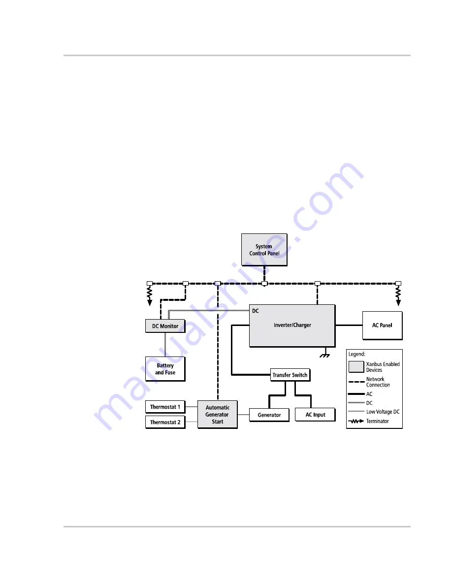
The Xanbus system includes the RS2000 Sine Wave Inverter/Charger and other
Xanbus-enabled devices, as shown in Figure 1, “Typical Xanbus System
Diagram”. Each Xanbus-enabled device interacts and communicates with the
other devices on the network, creating a power system that can be precisely
configured to your needs.
The RS2000 is the device that typically provides power in a Xanbus system. The
System Control Panel provides configuration and monitoring capability for each
device connected to the Xanbus system, such as the Automatic Generator Start
and the RS2000.
In Figure 1, network connections are represented by dotted lines and conventional
electrical connections are represented by solid lines. Your system requirements
may be more complex than the basic installation shown in Figure 1. Xantrex
recommends that you consult a qualified installer or electrican to customize your
installation to meet your requirements.
Figure 1
Typical Xanbus System Diagram
AC In
AC Out
Содержание RS2000
Страница 1: ...RS2000 Sine Wave Inverter Charger Installation Guide RS2000...
Страница 2: ......
Страница 3: ...RS2000 Sine Wave Inverter Charger Installation Guide...
Страница 8: ...iv 975 0126 01 01...
Страница 16: ...xii...
Страница 18: ...xiv...
Страница 49: ...Installation 975 0126 01 01 31 Figure 12 Connecting the BTS Cable to Battery Temp jack...
Страница 56: ...Installation 38 975 0126 01 01 Figure 15 Inverter Charger Dimensions...
Страница 75: ......


