P P G D I G I M A T C H
S P E C T R O P H O T O M E T E R
12
USER INTERFACE
The device features a graphical touch screen display. All functionality is accessed directly through the screen.
Main Screen Description
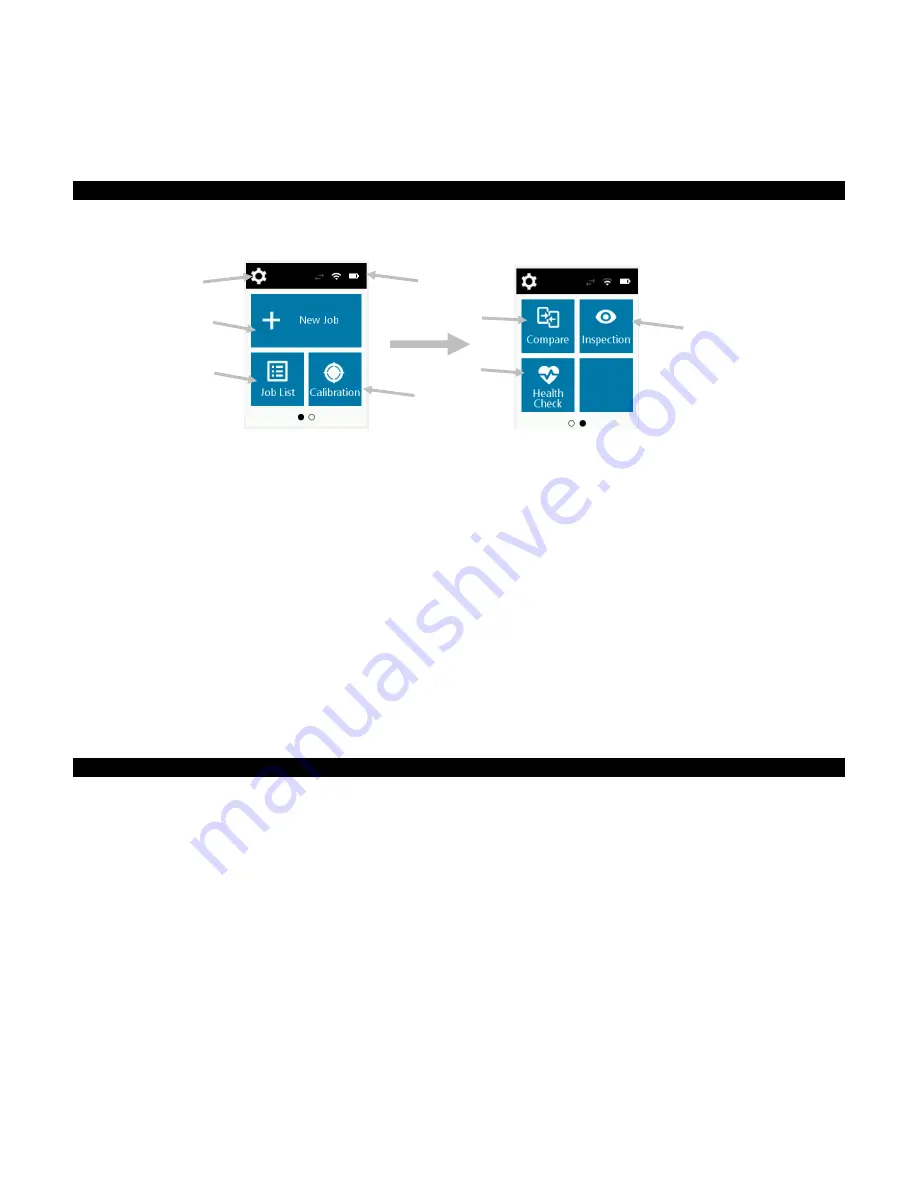
When the device is powered-up, the main (top level) screen appears after the diagnostics test is complete. The
main screen consists of the top bar and operation modes. Select the modes by tapping the icons located on the
display screen. Swipe the screen to the left to view the other operation modes.
(1)
Settings:
Used to set and edit the device configuration options and power the device off. The settings
options should be reviewed before you use your device for the first time. Refer to the Settings Mode section
for information.
(2)
Status Icons:
Displays the battery charge level, Wi-Fi connection, and software connection status (green
when connected).
(3)
New Job:
This mode is the main mode of operation. Sample measurements are taken and saved in this
mode. Refer to Creating a Job and Sample Measurement section for information.
(4)
Job List:
This mode is used to measure stored jobs and edit existing stored jobs. Refer to Creating a Job
and Sample Measurement section for information.
(5)
Calibrate:
This mode is used to calibrate the device. Refer to the Calibration section for information.
(6)
Compare:
This mode is a simple QC tool used to compare two samples. Refer to Compare Mode section
for information.
(7)
Health Check:
This function is used to perform a system check of the device. Refer Health Check section
for Information.
(8)
Inspection
: This mode is used to preview a measurement zone. Refer to Inspection Mode for information.
Pressure Sensors and Indicators
To aid in proper positioning and ensure repeatability of sample measurements, the device incorporates three
pressure sensors that are arranged around the measurement port. These sensors require an even amount of
contact to be applied across all three sensors before a measurement is triggered.
Three positioning indicators that appear in the screen as well as the indicator LEDs on the top of the device
provide positioning feedback. The indicators in the screen are arranged in the same pattern (top, back/side) as
the contact sensors located around the measurement port.
Green Indicator:
ideal contact is being applied to the corresponding sensor. A measurement can be
taken when all three indicators illuminate green. If the required contact is not maintained for the duration
of the measurement, an error message appears on the display and the measurement must be retaken.
Red Indicator:
the required contact is not being applied to the corresponding sensor. Correct contact
must be applied to achieve a green indicator condition.
(1)
(4)
(3)
(2)
(6)
(5)
(7)
(8)


