


Before Installation
4K @ 35m/114ft and 70m/230ft @1080p video are the maximum
recommended transmission distances for this model and
denotes recommended transmission conditions including
straight cable runs with no electrical interference, bends, kinks,
patch panels or wall outlets. If any of the above is a factor in your
installation, transmission range may be affected – take care to
avoid where possible.
We strongly recommend using supplied mounting brackets to
secure the receiver to a flat surface behind/near the display
device. Sudden movement of these devices could lead to loss of
picture/sound if connections become loose or strained, resulting
in unnecessary service call-backs.
If unsure of positioning, IR sensors can be located on devices by
shining a flashlight onto the fascia of the device - the IR sensor
should be identifiable as a small round sensor behind the panel.
Consult your device manufacturer handbook if difficulties are
experienced.
Setup and Operation
Connect a good quality, well-terminated Cat6 cable of no more
than 35m/114ft for 4K* or 70m/230ft for 1080p between the HDBT
or UTP OUT of the transmission device (matrix or transmitter) to
the HDBT IN or UTP IN Input of the RX-70-POH. If the transmission
device is PoH enabled, the PoH function will carry power along
the length of the cable to power the receiver so no local power is
required at display zones.
*4K transmission device required.
NOTE: Optional 12V power connectivity is available if
required - for example, if installation conditions, or cable
quality is too low to carry power, or if a non-PoH enabled
transmission device is being used.
Connect the HDMI display device to the HDMI OUT of the RX-70-
POH.
NOTE: a WyreStorm EXP-CON-4K-DD scaler may be
required for combined 4K and 1080p HD distributions.
See
wyrestorm.com
for more details
RX-70-POH
Quickstart Guide
WyreStorm HDBaseT PoH Display Receiver
with 2-Way IR and RS232
Check POWER, STATUS & LINK lights are illuminated on the
receiver to indicate successful connection, with a lit HDCP
illustrating the presence of encryption within the signal
NOTE: STATUS and HDCP LEDs should blink, POWER and
LINK are static LEDs.
Signal IR/RS232 Control Connection
For two-way IR control of connected source and display, connect
IR TX emitters from IR TX port of the transmission device and
receiver to the IR receiving area of the source on the display. Care
should be taken to firmly attach emitters directly over the infrared
receiving area of devices. Location of the emitter eye may need to
be adjusted later to achieve best IR performance.
For use with a control system, an IR Link cable (sold separately)
should be connected from the transmission device IR RX port to
the controller used. An IR receiver should be connected from the
IR RX port of the RX-70-POH to the display, placing the receiver
eye on or near the display in clear line of sight to the remote
handset used to control.
At both display and source locations, position the IR receiver in
clear line of sight to the remote handset used to control it, ensuring
the receiver is not obstructed.
For an RS232-based control system, an RS232 cable should be
used from transmission device to control system and between the
RX-70-POH and display to enable serial control between devices.
1
2
3
4
5
7
6
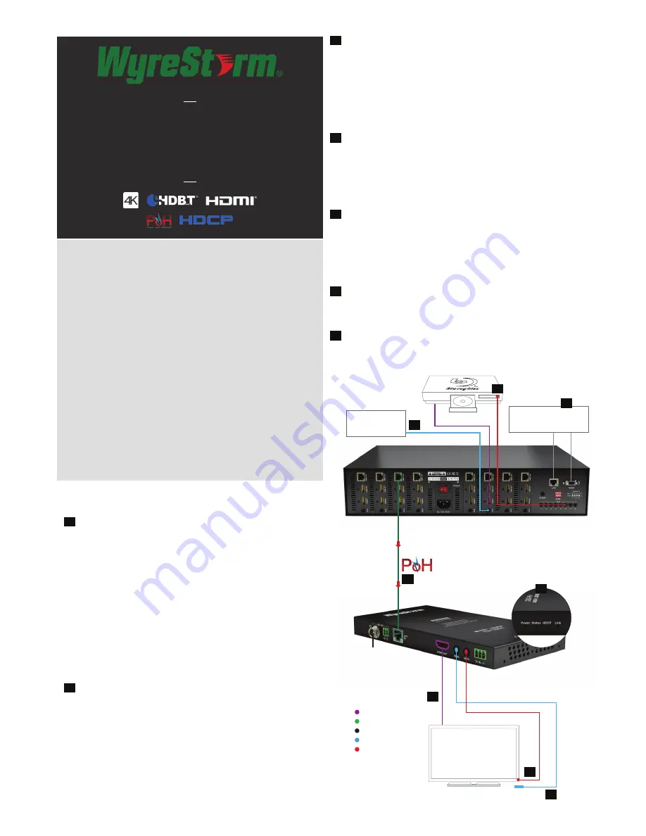
DISPLAY OUTPUT
RX-70-POH
Optional
Mains power
HDBaseT PoH-enabled transmission device
LAN / Serial based
Control System
IR based
Control System
Cat6
4K - 35m/114ft
1080p - 70m/230ft
1
2
3
4
7
5
5
4
NOTE: Although WyreStorm products are tested
with Cat5e, we recommend Cat6 as standard due
to increased bandwidth and improved capacity for
handling large transmissions along a single cable.
KEY
HDMI
HDBaseT Cat6
Power
IR RX
IR TX


