Assembly
17
MAN0160 (Rev. 8/19/2005)
MAIN ASSEMBLY - All Models
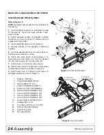
Attach Blade to Pivot Assembly
Assemble the main portion of the blade before start-
ing on any of the optional configurations.
1.
Place blade assembly (11) on floor with pivot
attachment pointing up.
2.
Raise the top end approximately 4" (102 mm)
above the ground with a wooden block. Place pivot
assembly (9) on blade assembly (11).
3.
Stack two shim washers (53) on each of the four
holes in blade. Place retainer assembly (10) on wash-
ers.
4.
Place washers (52) and lock washers (51) on
bolts (50) and insert through retainer (10), washers
(53), and pivot attachment (9).
5.
Secure by placing washers (52) and nuts (54) on
bolts and torque to 300 lbs.-ft (403 N-m).
Figure 1
Blade and Pivot Assembly
9.
Pivot assembly
10.
Retainer assembly
11.
RB750 Molboard assembly
11.
RB850 Molboard assembly
50.
Screw, HHCS 3/4 NC x 3 GR5
51
Washer, Lock 3/4
52.
Washer, Flat 3/4 Standard
53.
Washer, Shim .75 x 1.50 x 18ga
54.
Nut, Hex 3/4 NC
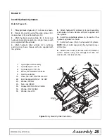
Attach Boom to Pivot Assembly
1.
Grease inside of tube on rear of boom (4).
2.
Set blade assembly upright. Place a block of
wood under pivot assembly to secure.
3.
Place boom parallel to blade and insert greased
tube over post of pivot assembly(9). Rotate boom 90
degrees to lock lip on rear of boom over pivot assem-
bly.
4.
Place jack stand under boom so boom is in a hor-
izontal position.
4.
Boom
9.
Pivot assembly
Figure 2
Boom and Blade Assembled
9
10
0
11
52
51
50
0
53
52
54
CD5979-2
4
Grease Tube
9
Lip


