Alignment
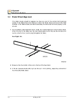
Blade Wheel Alignment
MHdoc012819
5-5
5
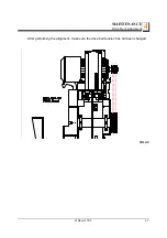
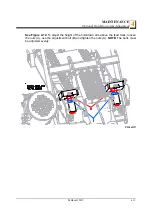
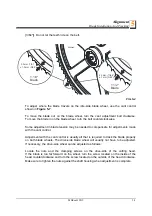
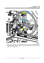
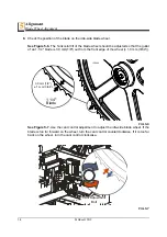
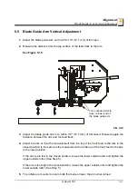
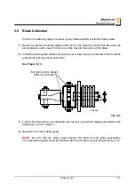
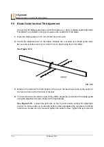
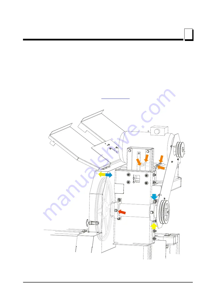
See Figure 5-4.
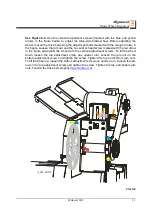
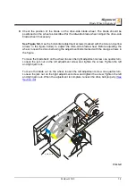
Use the vertical adjustment screws (marked with the blue and yellow
arrows in the figure below) to adjust the drive-side blade wheel. Before adjusting the
wheel, loosen the drive belt using the adjustment bolts marked with the orange arrows in
the figure. Loosen the jam nut and the hex socket head screw marked with the red arrow
in the figure and adjust the wheel with the vertical adjustment screws. To tilt the wheel
down, loosen the top adjustment screw one quarter turn. Loosen the jam nut on the
bottom adjustment screw and tighten the screw. Tighten the top and bottom jam nuts.
To tilt the wheel up, loosen the bottom adjustment screw one quarter turn. Loosen the jam
nut on the top adjustment screw and tighten the screw. Tighten the top and bottom jam
nuts. Tension the drive belt properly (
FIG. 5-4
rs_020_HR700
Содержание HR700 Series
Страница 1: ......
Страница 2: ......
Страница 35: ...Operation Electrical Requirements US Version Only Operation MHdoc012819 2 14 2 figure below FIG 2 9 ...

