background image

www.wolfvision.com

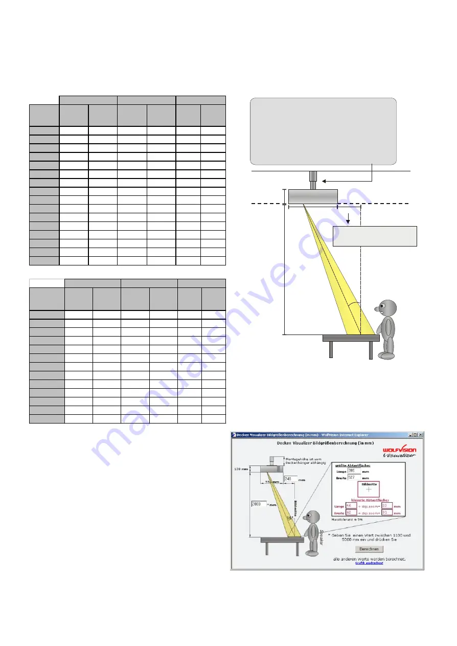
Verwenden Sie das Rechenprogramm auf 
www.wolfvision.com um die exakte Position 
und die Bildgröße zu berechnen.

* Der Abstand wird von der Unterseite des Decken 
Visualizers zum Tisch gemessen. Diese Werte können 
geringfügig abweichen, da die Stellung des Fokus die 
Bildgröße beeinflussen kann. Ebenso sollte die 
Maskierung des Projektors oder Monitors 
berücksichtigt werden (unter "Maskierung" versteht 
man das leichte Beschneiden der Bildränder). 
Theoretisch sind auch höhere Abstände als 4000mm 
möglich, jedoch mit den Nachteilen, dass das Bild zu 
groß und das Licht zu schwach werden würde.

Die Bildgrößen, die das Gerät aufnehmen kann, sind nicht fix. Sie sind abhängig vom Abstand zwischen der 
Arbeitsfläche und der Unterseite des Visualizers. Die folgende Tabelle zeigt das Verhältnis zwischen 
Montagehöhe und Aufnahmegröße:

INSTALLATION 

In extrem hohen Räumen ist 

das Gerät 

abtasten kann, möglicherweise nicht 
klein genug. In solchen Fällen kann der 
Decken Visualizer mit einem Standard 
Decken-hänger oder Projektorlift von 
der Decke abgehängt werden.

das 

kleinste Bild, welches 

7

A

b

s

ta

n

d

 (

s

ie

h

e

 T

a

b

e

lle

 n

e

b

e

n

a

n

)

Abgehängte Decke

(sofern erwünscht)

Decke

In inch

Dis tance  *

m ax. 

te le

le ngth

m ax. 

te le

w idth

m ax. 

te le

le ngth

m ax. 

te le

w idth

m ax. 

w ide

le ngth

m ax. 

w ide

w idth

40" (3.33')

0.49"

0.66"

0.98"

1.31"

8.35"

11.14"

50" (4.17')

0.60"

0.80"

1.20"

1.60"

10.22"

13.62"

60" (5.00')

0.71"

0.95"

1.42"

1.89"

12.08"

16.10"

70" (5.83')

0.82"

1.09"

1.64"

2.19"

13.93"

18.58"

80" (6.67')

0.93"

1.24"

1.86"

2.48"

15.80"

21.06"

90" (7.50')

1.04"

1.38"

2.08"

2.77"

17.65"

23.54"

100" (8.33')

1.15"

1.53"

2.30"

3.06"

19.52"

26.02"

110" (9.17')

1.26"

1.68"

2.51"

3.35"

21.37"

28.50"

120"(10.00')

1.37"

1.82"

2.73"

3.64"

23.24"

30.98"

130"(10.83')

1.48"

1.97"

2.95"

3.94"

25.10"

33.47"

140"(11.67')

1.59"

2.11"

3.17"

4.23"

26.95"

35.94"

150"(12.50')

1.70"

2.26"

3.39"

4.52"

28.82"

38.42"

160"(13.33')

1.80"

2.41"

3.61"

4.81"

30.67"

40.90"

m ax. digital zoom m ax. optical zoom

m ax. w ide

In mm

Abstand *

Max. Tele 

Länge

Max. Tele 

Breite

Max. Tele 

Länge

Max. Tele 

Breite

Max. 

Wide 

Länge

Max. 

Wide 

Breite

1.000

12

16

25

33

209

279

1.200

14

19

29

39

246

329

1.400

17

22

33

44

284

378

1.600

19

25

38

50

321

428

1.800

21

28

42

56

358

477

2.000

23

31

46

62

395

527

2.200

25

34

51

68

432

577

2.400

28

37

55

74

470

626

2.600

30

40

60

80

507

676

2.800

32

43

64

85

544

725

3.000

34

46

68

91

581

775

3.200

36

49

73

97

618

825

3.400

39

51

77

103

656

874

3.600

41

54

82

109

693

924

3.800

43

57

86

115

730

973

4.000

45

60

90

120

767

1.023

max. digital Zoom

max. optisches Zoom

max. Weitwinkel

16

o

130mm
5.1 inch

553mm/ 21.8 inch

x

V

o

rtr

a

g

e

n

d

e

r

x mm = 

Abstand

 * 0.2867 - 325mm

x"       = 

Abstand

 * 0.2867 - 12.795"

siehe Installationsanleitung Seite 3

Содержание VZ-C10

Страница 1: ...SCH R Check out our Internet Homepage for additional information at http www wolfvision com support VZ C10 VZ C10 Weitere technische Informationen finden Sie auf unserer Internet Homepage unter http w...

Страница 2: ...that sufficient air circulation for cooling the unit is possible ventilation slots on the left and right side of the unit If there is any abnormality abnormal noise smell smoke etc turn the power off...

Страница 3: ...ve Blue and Black White DVI port Serial port and Serial protocol Software upgrades Technical data Dimensions Troubleshooting Detailed settings of the on screen menu 3 Manufacturer Wolf Vision GmbH Vlb...

Страница 4: ...TURN A A FOCUS IRIS MENU HELP EXT INT LIGHT TEXT LASER 12 14 15 19 20 17 18 16 24 25 13 22 23 21 1 Mirror light 2 Mirror camera 3 Infrared sensor 1 bottom 4 Infrared sensor 2 front side 5 Synchronize...

Страница 5: ...er resolutions than their native resolution but only in compressed mode and with inferior picture quality Do NOT set the output of the Visualizer to a higher standard than the native resolution of you...

Страница 6: ...ight motorized f mirror camera g pickup area synchronized lightfield HOW THE VISUALIZER WORKS BASIC PREPARATIONS 6 A light projector a inside the unit projects a lightfield g the same size as the pick...

Страница 7: ...00 12 16 25 33 209 279 1 200 14 19 29 39 246 329 1 400 17 22 33 44 284 378 1 600 19 25 38 50 321 428 1 800 21 28 42 56 358 477 2 000 23 31 46 62 395 527 2 200 25 34 51 68 432 577 2 400 28 37 55 74 470...

Страница 8: ...with the ZOOM keys 13 3 Adjust the sharpness with the FOCUS keys 17 if necessary WORKING ON THE WORKING SURFACE FOCUSING When the Visualizer is turned on the focus automatically adjusts to the working...

Страница 9: ...ly adjust the one push white balance Preparing the manual white balance adjustment Top light Zoom in on a white object for example a white sheet of paper until there is only white on the screen Lightb...

Страница 10: ...image off mode eliminating monitor image distortions when switching the outputs on and off 10 20 WolfVision Visualizers offer the possibility of programming three Presets for the functions Zoom Focus...

Страница 11: ...mode Image turn mode Only 50 of the pixels are used to pick up the letter 90 of the pixels are used to pick up the letter IMAGE TURN MODE for higher resolution If a computer is connected to the Exter...

Страница 12: ...is key combination is used the code switches from A to B C D A etc For resetting the remote control to code A simultaneously p 13 CLEANING ipe the mirror gently with a soft and lint free tissue no pap...

Страница 13: ...27 are situated in a fuse holder behind a small lid beside the power socket and the main power switch It can easily be opened with a small screwdriver etc Please make sure that the fuses are put in c...

Страница 14: ...NSPORTATION Please make sure that you pack up the Visualizer in the supplied box as explained in this graphic This is very important to avoid damage to sensitive parts of the unit IMPORTANT 14 5 4 3 2...

Страница 15: ...he cursor in the respective line and press the HELP key 21 A detailed description of this function appears on the screen only The functions of the o are described in the help menu of the Visualizer an...

Страница 16: ...eight see page 7 Max object height on working surface depending on mounting height 250mm 9 7 minimum Depth of focus Depth of field depending on mounting height the higher the better The following mini...

Страница 17: ...ARATE SYNC but not both at the same time see page 11 No stable picture Sync problems Check if the monitor or projector is capable to display the image output by the Visualizer If not select a lower ou...

Страница 18: ...E CONTROL 10 8 4 1 2 3 11 7 Printed in Austria November 2003 R Storing presets Auto focus for flat objects Press a PRESET key 14 for 2 sec Press MENU key 19 for 1 sec Displaying the on screen menu Man...

Страница 19: ...st L ftungsschlitze links und rechts unbedingt freihalten Bei jeder Art von St rungsanzeichen abnormale Ger usche Geruch Rauchentwicklung etc das Ger t abschalten Setzen Sie sich bitte in solchen F ll...

Страница 20: ...und Serielles Protokoll Software Upgrades Technische Daten Dimensionen St rungssuche Detaillierte Einstellungen f r das On Screen Men KONTAKTE Gedruckt in sterreich Technische nderungen vorbehalten N...

Страница 21: ...BEDIENUNG 10 8 4 1 2 3 11 7 4 1 Umlenkspiegel Licht 2 Umlenkspiegel Kamera 3 Infrarot Sensor 1 Unterseite 4 Infrarot Sensor 2 Vorderseite 5 Synchronisiertes Lichtfeld 6 Infrarot Fernbedienung 7 Haupts...

Страница 22: ...ps Ihres Projektors oder Monitors Die meisten LCD oder DLP Projektoren k nnen meist auch h here Bildaufl sungen darstellen jedoch nur im komprimierten Modus mit weit schlechterer Bildqualit t Stellen...

Страница 23: ...enkspiegel Kamera g Aufnahmebereich synchronisiertes Lichtfeld 6 INSTALLATION INBETRIEBNAHME DES VISUALIZERS Ein Lichtprojektor a im Ger teinneren projiziert ein Lichtfeld g in derselben Gr e wie der...

Страница 24: ...m ax tele w idth m ax tele length m ax tele w idth m ax w ide length m ax w ide w idth 40 3 33 0 49 0 66 0 98 1 31 8 35 11 14 50 4 17 0 60 0 80 1 20 1 60 10 22 13 62 60 5 00 0 71 0 95 1 42 1 89 12 08...

Страница 25: ...s Wei wertes Damit wird die Farbtemperatur unterschiedlicher Lichtquellen kompensiert siehe Seite 9 1 2 Die zu pr sentierende Vorlage auf die Arbeitsfl che legen Ein synchronisiertes Lichtfeld auf der...

Страница 26: ...eadfolien sehr wellig sind Wenn das Raumlicht Reflexionen auf der Overheadfolie verursacht ARBEITEN MIT OVERHEADFOLIEN 9 Weissabgleich WICHTIG Immer wenn sich die Lichtbedingungen ndern muss die Kamer...

Страница 27: ...s Dr cken der Taste Einen Preset abrufen Dr cken von mehr als 2 Sekunden Einen Preset speichern WolfVision Visualizer bieten die M glichkeit drei fixe Einstellungen f r die folgenden Funktionen zu spe...

Страница 28: ...der Pixel werden verwendet um die Vorlage darzustellen 90 der Pixel werden verwendet um die Vorlage darzustellen IMAGE TURN MODUS f r eine h here Aufl sung Wenn ein Computer an den Externen RGBHV Ein...

Страница 29: ...fl chen Spiegel Nur in vertikaler Richtung reinigen Horizontale Kratzer k nnen unsch ne Reflexionen bewirken Nicht zu stark reiben Wenn der Visualizer nur noch aus n chster N he bzw berhaupt nicht meh...

Страница 30: ...bdeckung beim Anschlussfeld Die Abdeckung ist mit einem Schraubenzieher zu ffnen Beim Einlegen der Sicherung ist auf die richtige Lage zu achten Der Sicherungs Typ ist T 3 15A Verwenden Sie ausschlie...

Страница 31: ...Bitte vergewissern Sie sich dass Sie den Visualizer genau nach unten stehender Anleitung in die mitgelieferte Box einpacken Dies ist sehr wichtig um Besch digungen an sensiblen Teilen des Ger tes zu...

Страница 32: ...on auf Englisch erscheint dann im Bild ZUR CKSETZEN DER ON SCREEN MEN EINSTELLUNGEN Einstellungen im On Screen Men k nnen auf die Werkseinstellungen zur ckgesetzt werden Reset ist ein Punkt im On Scre...

Страница 33: ...ch auf Arbeitsfl che Abh ngig von der Montageh he siehe Seite 7 Max Objekth he auf der Arbeitsfl che Abh ngig von der Montageh he mindestens 250mm Tiefensch rfe Abh ngig von Montageh he je h her desto...

Страница 34: ...siehe Seite 9 F hren Sie einen Wei abgleich bei Ihrem LCD oder DLP Projektor durch Bei zu viel Blau Entweder SYNC ON GREEN oder separaten SYNC verwenden Nicht beides gleichzeitig Siehe Seite 11 Pr fe...

Страница 35: ...n Deckel 10 8 4 1 2 3 11 7 Gedruckt in sterreich November 2003 R CODES FERNBEDIENUNG Presets speichern Autofokus f r flache Objekte Dr cken Sie eine PRESET Taste 14 f r 2 Sek Dr cken Sie die MEN Taste...

Страница 36: ...CONTROL 10 8 4 1 2 3 11 7 Printed in Austria November 2003 R Storing presets Auto focus for flat objects Press a PRESET key 14 for 2 sec Press MENU key 19 for 1 sec Displaying the on screen menu Manu...

Отзывы: