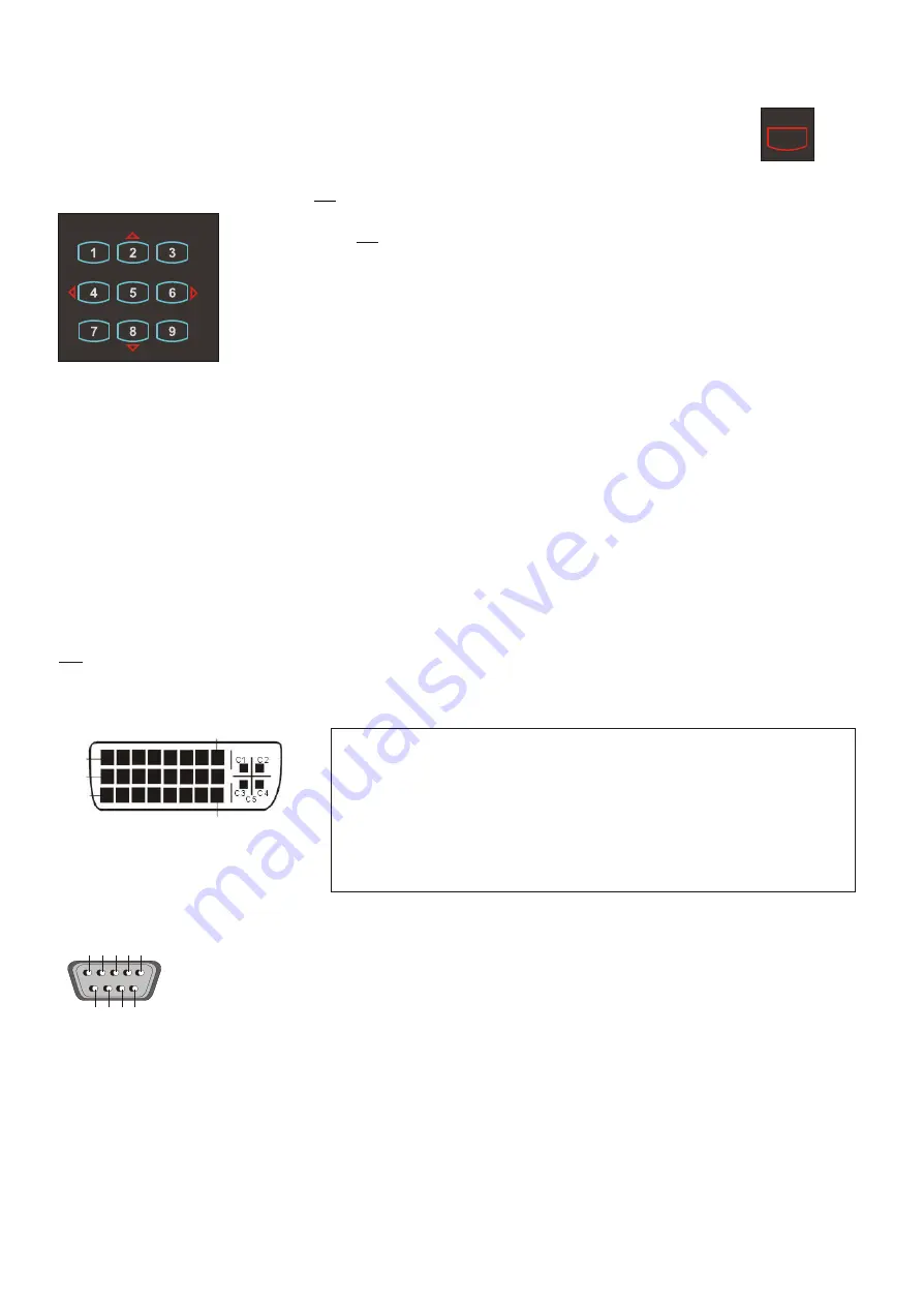
background image

DVI-I PORT 

SERIAL PORT / SERIAL PROTOCOL

Pins:             2:RX,  3:TX,  5:GND

9-pin D-Sub connector 
on unit, male, front side

A detailed description of the serial protocol (including status
report and position setting) is available on request from your 
WolfVision dealer or can be downloaded from our website: 

http://www.wolfvision.com/support.

Pin 1

Pin 24

Pin 8

Pin 9

Pin 17

  1  -  T.M.D.S. Data2-
  2  -  T.M.D.S. Data2+
  3  -  T.M.D.S. Data2/4 Shield
  4  -  T.M.D.S. Data4- 

(not used)

  5  -  T.M.D.S. Data4+

(not used)

  6  -  DDC Clock
  7  -  DDC Data
  8  -  Analog Vertical Sync
C1 -  Analog Red
C4 -  Analog Horizontal Sync 

  9  -  T.M.D.S. Data1-
10  -  T.M.D.S. Data1+
11  -  T.M.D.S. Data1/3 Shield
12  -  T.M.D.S. Data3- 

(not used)

13  -  T.M.D.S. Data3+ 

(not used)

14  -  +5V Power
15  -  Ground (return for +5V, 
         HSync and VSync)
16  -  Hot Plug Detect
C2 -  Analog Green
C5 -  Analog Ground
         (analog R, G & B return) 

17  -  T.M.D.S. Data0-
18  -  T.M.D.S. Data0+
19  -  T.M.D.S. Data0/5 Shield
20  -  T.M.D.S. Data5- 

(not used)

21  -  T.M.D.S. Data5+ 

(not used)

22  -  T.M.D.S. Clock+
23  -  T.M.D.S. Clock-
24  -  Analog Vertical Sync
C3 -  Analog Blue

For standard use of the WolfVision Visualizer it is NOT necessary to enter the Visualizer's menu and change
settings. Inexperienced users should not try to make any adjustments there.

ON-SCREEN MENU / CAMERA-MENU

FIRMWARE UPGRADES

The following chapters are for experienced users only!

For entering the Visualizer's menu press the Menu key (#19) 

for 1 second.


(The menu does not appear when the menu key is 

pressed quickly. This is to 

prevent that inexperienced users enter the menu by mistake).

When the menu appears on the screen, settings of the Visualizer's basic functions and 
the built-in camera can be made using the 4 select keys

 (#22).


If you require more information on a function in the on-screen menu just set the cursor 
in the respective line and press the HELP key 

(#21). 

A detailed description of this 

function appears on the screen. 

only 

The functions of the o

 are described in the help menu of the Visualizer and not in this user manual.

This is because the help texts are an integrated part of the Visualizer's software (firmware) and always refer to the 
firmware version which is currently loaded on your Visualizer. 

n-screen menu

The software (firmware) of your Visualizer (including the o

) can easily be upgraded to the latest 

version. First download the latest firmware and WolfVision's firmware update utility program from Wolfvision's
internet homepage at www.wolfvision.com/support. Then connect the serial port of the Visualizer with 
the serial port of your computer using a crossed serial RS232 cable and run the firmware update utility program.

More details on the firmware updates can be found on WolfVision's internet homepage.

n-screen HELP

RESET OF ON-SCREEN-MENU SETTINGS / PRESETS

The settings in the 

 can be set back to the factory defaults. "Reset" is an item in the on-screen 

Menu. The on-screen menu also offers the possibility to store three different menu settings as menu-presets.

on-screen menu

SWITCHING TO NEGATIVE, NEGATIVE/BLUE and BLACK/WHITE

The output image of the Visualizer can be switched from positive to negative in the on-screen menu. In addition the 
background of a negative image can be switched to blue for better readability of text. You can also switch between 
color and black/white in the 

.

TIP: If the negative, negative/blue or black/white images are often required, you can assign this function to one of  
the Preset keys

 (#14) 

in the 

.

on-screen menu

on-screen menu

5

9

2

7

3 4

8

1

6

15

MEMORY

HELP

22

21

MENU

19

DVI-I ports are divided into a digital and 
an analog section. Please note that the 
image of the External input 

(#32)

 is only 

output at the analog DVI section!

Содержание VZ-C10

Страница 1: ...SCH R Check out our Internet Homepage for additional information at http www wolfvision com support VZ C10 VZ C10 Weitere technische Informationen finden Sie auf unserer Internet Homepage unter http w...

Страница 2: ...that sufficient air circulation for cooling the unit is possible ventilation slots on the left and right side of the unit If there is any abnormality abnormal noise smell smoke etc turn the power off...

Страница 3: ...ve Blue and Black White DVI port Serial port and Serial protocol Software upgrades Technical data Dimensions Troubleshooting Detailed settings of the on screen menu 3 Manufacturer Wolf Vision GmbH Vlb...

Страница 4: ...TURN A A FOCUS IRIS MENU HELP EXT INT LIGHT TEXT LASER 12 14 15 19 20 17 18 16 24 25 13 22 23 21 1 Mirror light 2 Mirror camera 3 Infrared sensor 1 bottom 4 Infrared sensor 2 front side 5 Synchronize...

Страница 5: ...er resolutions than their native resolution but only in compressed mode and with inferior picture quality Do NOT set the output of the Visualizer to a higher standard than the native resolution of you...

Страница 6: ...ight motorized f mirror camera g pickup area synchronized lightfield HOW THE VISUALIZER WORKS BASIC PREPARATIONS 6 A light projector a inside the unit projects a lightfield g the same size as the pick...

Страница 7: ...00 12 16 25 33 209 279 1 200 14 19 29 39 246 329 1 400 17 22 33 44 284 378 1 600 19 25 38 50 321 428 1 800 21 28 42 56 358 477 2 000 23 31 46 62 395 527 2 200 25 34 51 68 432 577 2 400 28 37 55 74 470...

Страница 8: ...with the ZOOM keys 13 3 Adjust the sharpness with the FOCUS keys 17 if necessary WORKING ON THE WORKING SURFACE FOCUSING When the Visualizer is turned on the focus automatically adjusts to the working...

Страница 9: ...ly adjust the one push white balance Preparing the manual white balance adjustment Top light Zoom in on a white object for example a white sheet of paper until there is only white on the screen Lightb...

Страница 10: ...image off mode eliminating monitor image distortions when switching the outputs on and off 10 20 WolfVision Visualizers offer the possibility of programming three Presets for the functions Zoom Focus...

Страница 11: ...mode Image turn mode Only 50 of the pixels are used to pick up the letter 90 of the pixels are used to pick up the letter IMAGE TURN MODE for higher resolution If a computer is connected to the Exter...

Страница 12: ...is key combination is used the code switches from A to B C D A etc For resetting the remote control to code A simultaneously p 13 CLEANING ipe the mirror gently with a soft and lint free tissue no pap...

Страница 13: ...27 are situated in a fuse holder behind a small lid beside the power socket and the main power switch It can easily be opened with a small screwdriver etc Please make sure that the fuses are put in c...

Страница 14: ...NSPORTATION Please make sure that you pack up the Visualizer in the supplied box as explained in this graphic This is very important to avoid damage to sensitive parts of the unit IMPORTANT 14 5 4 3 2...

Страница 15: ...he cursor in the respective line and press the HELP key 21 A detailed description of this function appears on the screen only The functions of the o are described in the help menu of the Visualizer an...

Страница 16: ...eight see page 7 Max object height on working surface depending on mounting height 250mm 9 7 minimum Depth of focus Depth of field depending on mounting height the higher the better The following mini...

Страница 17: ...ARATE SYNC but not both at the same time see page 11 No stable picture Sync problems Check if the monitor or projector is capable to display the image output by the Visualizer If not select a lower ou...

Страница 18: ...E CONTROL 10 8 4 1 2 3 11 7 Printed in Austria November 2003 R Storing presets Auto focus for flat objects Press a PRESET key 14 for 2 sec Press MENU key 19 for 1 sec Displaying the on screen menu Man...

Страница 19: ...st L ftungsschlitze links und rechts unbedingt freihalten Bei jeder Art von St rungsanzeichen abnormale Ger usche Geruch Rauchentwicklung etc das Ger t abschalten Setzen Sie sich bitte in solchen F ll...

Страница 20: ...und Serielles Protokoll Software Upgrades Technische Daten Dimensionen St rungssuche Detaillierte Einstellungen f r das On Screen Men KONTAKTE Gedruckt in sterreich Technische nderungen vorbehalten N...

Страница 21: ...BEDIENUNG 10 8 4 1 2 3 11 7 4 1 Umlenkspiegel Licht 2 Umlenkspiegel Kamera 3 Infrarot Sensor 1 Unterseite 4 Infrarot Sensor 2 Vorderseite 5 Synchronisiertes Lichtfeld 6 Infrarot Fernbedienung 7 Haupts...

Страница 22: ...ps Ihres Projektors oder Monitors Die meisten LCD oder DLP Projektoren k nnen meist auch h here Bildaufl sungen darstellen jedoch nur im komprimierten Modus mit weit schlechterer Bildqualit t Stellen...

Страница 23: ...enkspiegel Kamera g Aufnahmebereich synchronisiertes Lichtfeld 6 INSTALLATION INBETRIEBNAHME DES VISUALIZERS Ein Lichtprojektor a im Ger teinneren projiziert ein Lichtfeld g in derselben Gr e wie der...

Страница 24: ...m ax tele w idth m ax tele length m ax tele w idth m ax w ide length m ax w ide w idth 40 3 33 0 49 0 66 0 98 1 31 8 35 11 14 50 4 17 0 60 0 80 1 20 1 60 10 22 13 62 60 5 00 0 71 0 95 1 42 1 89 12 08...

Страница 25: ...s Wei wertes Damit wird die Farbtemperatur unterschiedlicher Lichtquellen kompensiert siehe Seite 9 1 2 Die zu pr sentierende Vorlage auf die Arbeitsfl che legen Ein synchronisiertes Lichtfeld auf der...

Страница 26: ...eadfolien sehr wellig sind Wenn das Raumlicht Reflexionen auf der Overheadfolie verursacht ARBEITEN MIT OVERHEADFOLIEN 9 Weissabgleich WICHTIG Immer wenn sich die Lichtbedingungen ndern muss die Kamer...

Страница 27: ...s Dr cken der Taste Einen Preset abrufen Dr cken von mehr als 2 Sekunden Einen Preset speichern WolfVision Visualizer bieten die M glichkeit drei fixe Einstellungen f r die folgenden Funktionen zu spe...

Страница 28: ...der Pixel werden verwendet um die Vorlage darzustellen 90 der Pixel werden verwendet um die Vorlage darzustellen IMAGE TURN MODUS f r eine h here Aufl sung Wenn ein Computer an den Externen RGBHV Ein...

Страница 29: ...fl chen Spiegel Nur in vertikaler Richtung reinigen Horizontale Kratzer k nnen unsch ne Reflexionen bewirken Nicht zu stark reiben Wenn der Visualizer nur noch aus n chster N he bzw berhaupt nicht meh...

Страница 30: ...bdeckung beim Anschlussfeld Die Abdeckung ist mit einem Schraubenzieher zu ffnen Beim Einlegen der Sicherung ist auf die richtige Lage zu achten Der Sicherungs Typ ist T 3 15A Verwenden Sie ausschlie...

Страница 31: ...Bitte vergewissern Sie sich dass Sie den Visualizer genau nach unten stehender Anleitung in die mitgelieferte Box einpacken Dies ist sehr wichtig um Besch digungen an sensiblen Teilen des Ger tes zu...

Страница 32: ...on auf Englisch erscheint dann im Bild ZUR CKSETZEN DER ON SCREEN MEN EINSTELLUNGEN Einstellungen im On Screen Men k nnen auf die Werkseinstellungen zur ckgesetzt werden Reset ist ein Punkt im On Scre...

Страница 33: ...ch auf Arbeitsfl che Abh ngig von der Montageh he siehe Seite 7 Max Objekth he auf der Arbeitsfl che Abh ngig von der Montageh he mindestens 250mm Tiefensch rfe Abh ngig von Montageh he je h her desto...

Страница 34: ...siehe Seite 9 F hren Sie einen Wei abgleich bei Ihrem LCD oder DLP Projektor durch Bei zu viel Blau Entweder SYNC ON GREEN oder separaten SYNC verwenden Nicht beides gleichzeitig Siehe Seite 11 Pr fe...

Страница 35: ...n Deckel 10 8 4 1 2 3 11 7 Gedruckt in sterreich November 2003 R CODES FERNBEDIENUNG Presets speichern Autofokus f r flache Objekte Dr cken Sie eine PRESET Taste 14 f r 2 Sek Dr cken Sie die MEN Taste...

Страница 36: ...CONTROL 10 8 4 1 2 3 11 7 Printed in Austria November 2003 R Storing presets Auto focus for flat objects Press a PRESET key 14 for 2 sec Press MENU key 19 for 1 sec Displaying the on screen menu Manu...

Отзывы: