M-Series HMI
Mounting Solutions
User Manual
69
• Keep the wires separated according to the interface. Wires that share similar
electrical characteristics must be bundled together.
• Do not bundle input wiring with output wiring. Keep them separate.
When necessary, it is strongly advised that you label wiring to all devices in the
system.
6.3 Mounting Guide
M-series HMI devices come with different mounting options suitable for most of the
industrial and commercial applications. The main mounting approach is chassis - very
user-friendly in terms of installation. Refer to sub-sections below for more details.
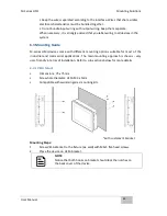
6.3.1 VESA Mount
•
Dimensions: 75 x 75mm
•
Screw hole diameter: VESA M4 x 5mm
•
Compatible with swimming arms mounting kits.
*with customer’s bracket
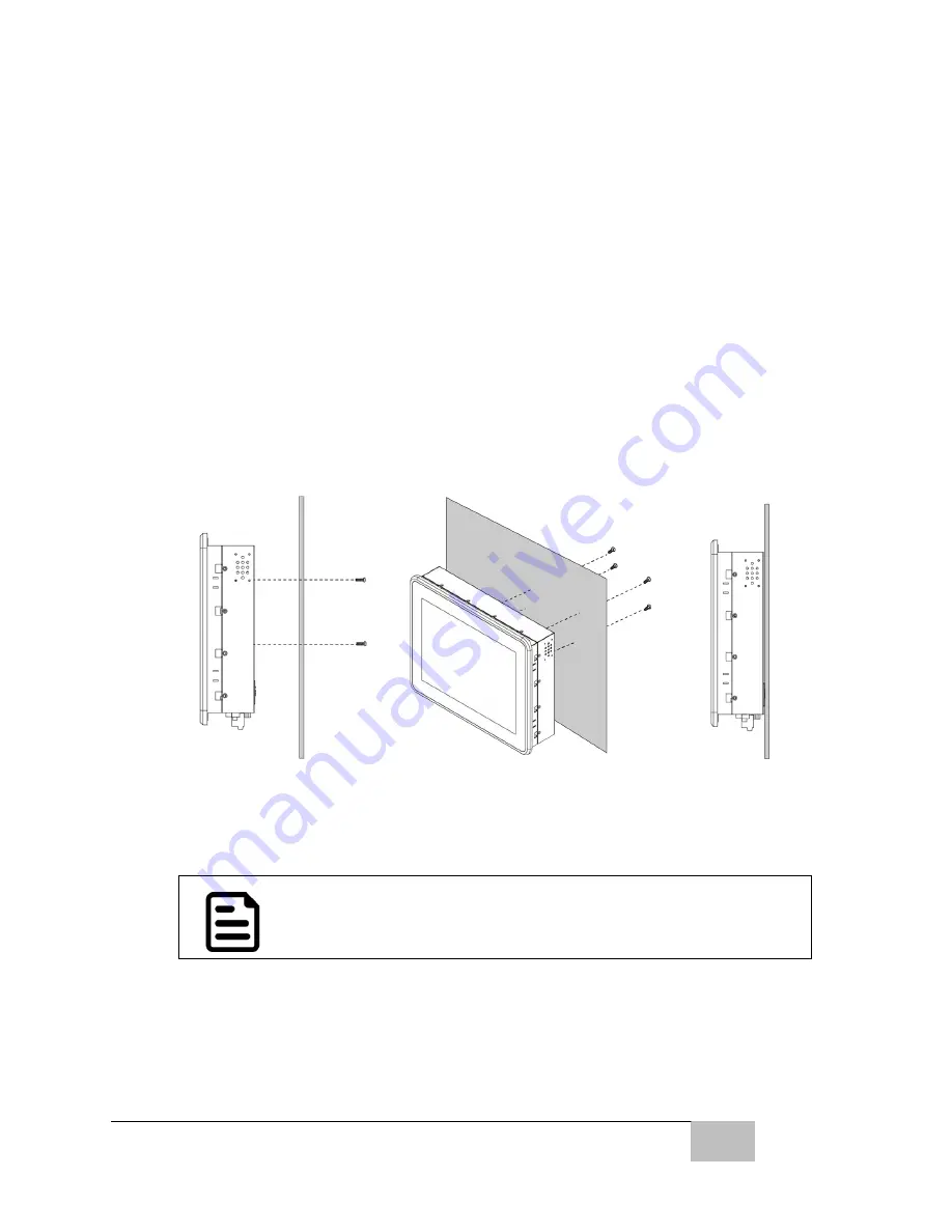
Mounting Steps:
1.
Screw VESA Bracket to the fixture (ex. wall) with M4x5 flat-head screws.
2.
Place the device on VESA bracket.
NOTE:
Notice that both hooks on bracket should lock the notches on
the back cover of the device.
Содержание R10IBWS-MHP1
Страница 11: ...User Manual xi 8 2 1 R10IBWS MHP1 77 8 2 2 R12IBWS MHM2 78...
Страница 16: ...M Series HMI Introduction User Manual 16 1 5 Appearance COM3 is an optional connector...
Страница 17: ...M Series HMI Introduction User Manual 17 1 6 Dimensions 10 4 Dimensions...
Страница 18: ...M Series HMI Introduction User Manual 18 12 1 Dimensions...
Страница 76: ...M Series HMI Certificates User Manual 76 8 1 2 R12IBWS MHM2...


