M-Series HMI
Getting Started
User Manual
25
Note:
A pair of needle nose pliers may be helpful when working with jumpers. If
you have any doubts about the best hardware configuration for your
application, contact your local distributor or sales representative before
you make any changes. Generally, you simply need a standard cable to
make most connections.
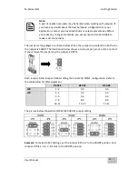
The jumper setting diagram is shown below. When the jumper cap is placed on both pins,
the jumper is SHORT. The illustration below shows a 3-pin jumper; pins 1 and 2 are short.
If you remove the jumper cap, the jumper is OPEN.
Both Jumper 8 and Jumper 9 allow setting the Serial Port COM1 configuration.
Refer to
the table below for PIN assignment.
The picture below shows RS-232/422/485 (J8/J9) jumper setting.
Example:
To make RS-232 Settings, set the Jumper 8 Pin 1-2 to the SHORT position, and
Jumper 9 Pin1-2, 4-5, 7-8, 10-11 to the SHORT position.
RS-232
RS-422
RS-485
JP8
1-2
3-4
5-6
JP9
1-2
4-5
7-8
10-11
2-3
5-6
8-9
11-12
2-3
5-6
8-9
11-12
Содержание R10IBWS-MHP1
Страница 11: ...User Manual xi 8 2 1 R10IBWS MHP1 77 8 2 2 R12IBWS MHM2 78...
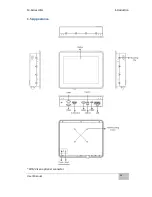
Страница 16: ...M Series HMI Introduction User Manual 16 1 5 Appearance COM3 is an optional connector...
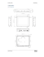
Страница 17: ...M Series HMI Introduction User Manual 17 1 6 Dimensions 10 4 Dimensions...
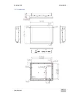
Страница 18: ...M Series HMI Introduction User Manual 18 12 1 Dimensions...
Страница 76: ...M Series HMI Certificates User Manual 76 8 1 2 R12IBWS MHM2...


