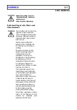


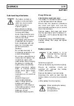

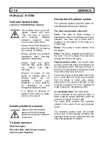


Hydraulic System Safety
(see also "Safe Working" section)
Do not allow oils to come into
regular contact with skin.
This can lead to serious
skin diseases. Medical
evidence suggests they
may include skin cancer.
Always wear protective gloves
when handling oils for topping
up, draining, or refilling.
Always practice the greatest
cleanliness when servicing
hydraulic components.
Always clean the areas
surround filler points, filters
etc., before and after
servicing.
Dispose of waste oil into
waste oil storage tanks. if
storage tanks are not
available, consult your
Distributor or local authority
for addresses of local
designated disposal points.
It is illegal to dispose of
waste oil into drains or water
courses or to bury it.
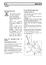
Dumping hydraulic pressure
Always dump all hydraulic
pressure from the system
before servicing any hydraulic
component.
To dump pressure:
Stop the engine.
Move the skip control lever several
times in each direction.
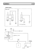
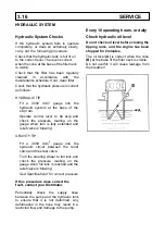
Description of hydraulic system
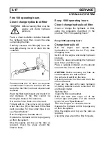
The hydraulic system provides power for
skip tipping and the power steering.
The main components consist of:
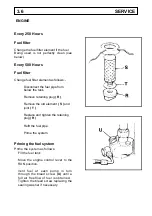
Tank:
The tank is filled through a
filler/strainer which incorporates an oil level
indicator. The filler cap is fitted with a
breather. In the bottom of the tank is a
suction filter.
Pump:
The pump is driven directly from
the engine
Filter:
The filter is situated in the bottom of
the tank. The oil is drawn from the tank,
through the filter to the pump.
Tipping control valve:
The control valve
receives oil from the pump and delivers it to
the skip tipping rams. The rate of oil flow to
the rams is proportional to the distance that
the control valve lever is moved.
If the control lever is held either fully to the
left or right after the rams have reached
their full stroke, a relief valve opens,
allowing the oil to return to the tank. A high
pressure carryover (H.P.C.O.) supplies oil
under pressure to the steering valve.
In Line Relief Valve:
The inline relief
Valve, mounted on the hydraulic tank, is
fitted to gravity tipping machines which do
not have a Tipping Control Valve.
The relief valve protects the hydraulic
system in the event of an over pressure
event.
The hydraulic system does not provide
priority flow to the steering, therefore the
steering should not be operated when the
skip is being tipped or lowered.
3.14 SERVICE
HYDRAULIC SYSTEM
Содержание 2B1500
Страница 2: ......
Страница 14: ...1 8 SAFE WORKING...
Страница 38: ...SERVICE 3 15...
Страница 44: ...4 4 TECHNICAL INFORMATION MAIN ELECTRICAL CIRCUIT without road lights TECHNICAL INFORMATION 4 5...
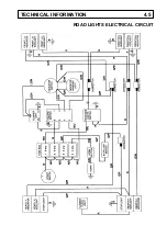
Страница 45: ...ROAD LIGHTS ELECTRICAL CIRCUIT TECHNICAL INFORMATION 4 5...
Страница 46: ......
Страница 47: ...2B1500 DUMPERS PARTS...
Страница 48: ......
Страница 50: ......
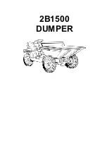
Страница 51: ...2B1500 DUMPER...
Страница 52: ......
Страница 54: ...A 1 2B1500 Dumper...
Страница 56: ...A 1B 2B1500 Dumper...
Страница 58: ...A 1D 2B1500 Dumper...
Страница 60: ...A 1E 2B1500 Dumper...
Страница 62: ...A 2 2B1500 Dumper...
Страница 64: ...A 3 2B1500 Dumper DSK 6...
Страница 66: ......
Страница 67: ...2B1500 DUMPER...
Страница 68: ......
Страница 70: ...B 1 2B1500 Dumper...
Страница 72: ...B 2 2B1500 Dumper...
Страница 74: ...B 2A 2B1500 Dumper DAX 33...
Страница 76: ...B 2B 2B1500 Dumper V601139 issue 02 0297...
Страница 78: ...B 2C 2B1500 Dumper DAX 41...
Страница 80: ...B 2D 2B1500 Dumper DAX 41...
Страница 82: ...B 3 2B1500 Dumper...
Страница 84: ...B 3 2B1500 Dumper DAX 9A...
Страница 86: ......
Страница 87: ...4B2000 DUMPERS 2B1500 DUMPER...
Страница 88: ......
Страница 90: ...C 1 2B1500 Dumper...
Страница 92: ...C 1 2B1500 Dumper...
Страница 94: ...C 1 2B1500 Dumper...
Страница 96: ...C 2 2B1500 Dumper DTR 2B...
Страница 98: ...C 3 2B1500 Dumper DCO 11...
Страница 100: ...C 4 2B1500 Dumper...
Страница 102: ......
Страница 103: ...2B1500 DUMPER...
Страница 104: ......
Страница 105: ...Brakes HANDBRAKE CABLE CALIPER D 1 CALIPER D 2 BRAKE PEDAL D 3 BRAKE HOSES FITTINGS D 4...
Страница 106: ...D 1 2B1500 Dumper...
Страница 108: ...D 2 2B1500 Dumper DCO 15...
Страница 110: ...D 3 2B1500 Dumper DCO 11A...
Страница 112: ...D 4 2B1500 Dumper...
Страница 114: ......
Страница 115: ...2B1500 DUMPER...
Страница 116: ......
Страница 117: ...Engine Controls LISTER PETTER TR1 ENGINE E 1 ACCELERATOR PEDAL LINKAGE E 2...
Страница 118: ...E 1 2B1500 Dumper...
Страница 120: ...E 2 2B1500 Dumper...
Страница 122: ......
Страница 123: ...2B1500 DUMPER...
Страница 124: ......
Страница 126: ...F 1 2B1500 Dumper...
Страница 128: ...F 2 2B1500 Dumper DEL 27...
Страница 130: ...F 3 2B1500 Dumper DEL 26...
Страница 132: ...F 3 2B1500 Dumper DEL 26...
Страница 134: ...F 4 2B1500 Dumper DEL 25...
Страница 136: ......
Страница 137: ...2B1500 DUMPER...
Страница 138: ......
Страница 140: ...H 1 2B1500 Dumper...
Страница 142: ...H 1A 2B1500 Dumper DHY 47...
Страница 144: ...H 1A 2B1500 Dumper DHY 47...
Страница 146: ...H 1AA 2B1500 Dumper...
Страница 148: ...H 2 2B1500 Dumper...
Страница 150: ...H 3 2B1500 Dumper...
Страница 152: ...H 4 2B1500 Dumper...
Страница 154: ...H 5 2B1500 Dumper...
Страница 156: ...H 6 2B1500 Dumper...
Страница 158: ......
Страница 159: ...4B2000 DUMPERS 2B1500 DUMPER...
Страница 160: ......
Страница 161: ...Miscellaneous DECALS PLATES J 1 to J 3...
Страница 162: ...J 1 2B1500 Dumper...
Страница 164: ...J 2 2B1500 Dumper...
Страница 166: ...J 3 2B1500 Dumper...
Страница 168: ......
Страница 170: ......