


16
OPM-135/C
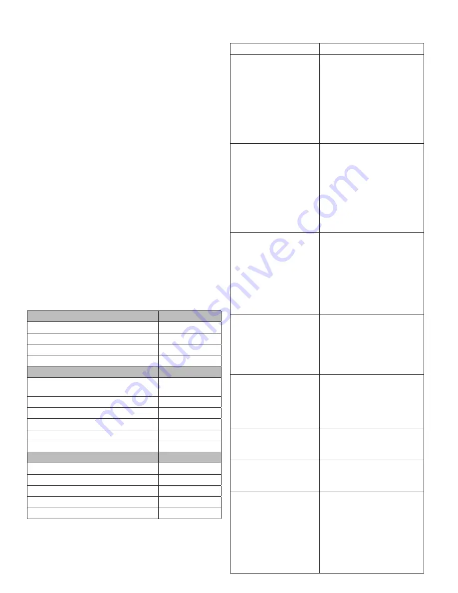
TROUBLESHOOTING TABLE
Problem
Possible Causes
Unit will not crank when
power fails
Digital genset not in AUTO
Transfer control switch not in
AUTOMATIC position
Incorrect wiring between ATS
and genset
Defective control relay in ATS
Fuse(s) blown in the DSE7310
Defective DSE7310
Loose or dirty battery terminals
Defective starter
Defective start solenoid
Low/dead battery
Engine won’t crank
Low/dead battery
Blown DC fuses
Defective DSE7310
Defective key switch
Loose or dirty battery terminals
Defective starter
Defective start solenoid
Locked up engine genset
Defective engine harness
Improper battery voltage to
start solenoid, fuel pump, or
fuel solenoid
Engine cranks but will not
start
Improper fuel delivery to the unit
Fuel supply shut off
Fuel tank empty
Air in the fuel system
Engine fuel solenoid has not
opened
Defective fuel pump
Defective fuel solenoid
Defective engine harness
Improper battery voltage to fuel
pump or fuel solenoid
Engine starts, then stops and
alarm light comes on
Engine oil pressure is low
Engine has high water
temperature
Engine has overspeed
Engine has gone into overcrank
No output from AC generator
Loss of speed signal
Loss of run signal
Engine will not come up to
speed after it starts
Insufficient fuel volume getting to
the unit
1. Too small of fuel line
2. Fuel racks not open properly
Governor is defective
AC short in generator
components
ATS will not transfer
to Emergency Supply
(generator)
No AC generator output
Defective ATS control board.
See ATS manual
Circuit breaker open or defective
ATS will not re-transfer to
normal power
Proper power line not available at
line terminals in ATS panel
Defective ATS control board.
See ATS manual
No AC output from generator Defective diode
Defective voltage regulator
Defective rotor
Defective stator
Defective exciter rotor
Defective exciter stator
AC short in the output leads
Defective/open generator output
breaker
Wiring error
protective liquid (ISO 4113) and introduce the liquid by
pressurizing the circuit and driving the engine for
approx. 2 min. after excluding injection system
operation.
The operation required can be completed by directly
polarizing terminal 50 of the electric starter motor with
positive voltage equal to that of the nominal system voltage,
using the designated conductor.
5. Nebulize the 30/M protective oil in a quantity of
approx. 130 g (10 g per liter of displacement) in the
turbocharger intake inlet, during the engine turning
operation described in the previous paragraph.
6. Close all of the engine’s intake, discharge, ventilation
and bleeding holes with plugs or seal them with
adhesive
tape.
7. Drain the residual 30/M protective oil from the sump,
which can be used for an additional 2 preparations.
8. Place warning notices of ENGINE WITHOUT OIL on the
engine and dashboard.
NOTE: When storing in cold regions, make sure the
coolant and engine oil are in conditions suitable to the
environment. Also, when starting the engine after it has
been stored, make sure that there is no snow or foreign
matter that could interfere with engine startup, and
rotating parts are not frozen.
MAINTENANCE SCHEDULE
Checks In Period of Use
Frequency
Check for water in the fuel filter
Daily
Check Air-Restriction Indicator on Filter Daily
Engine Oil Level
Daily/Prior to Use
Engine Coolant Level
Daily/Prior to Use
Planned Maintenance
Frequency
Tension and Condition Check of
Ancillary Belt
500 Hours
Engine Oil Replacement
250 Hours
Oil Filter Replacement
500 Hours
Fuel Filter Replacement
500 Hours
Clean Radiator
500 Hours
Air Filter Replacement
1250 Hours
Extraordinary Maintenance
Frequency
Ancillary Belt Replacement
3000 Hours
Turbocharger Visual Inspection
1500 Hours
Alternator Visual Inspection
3000 Hours
Clean/Replace Radiator Cap
3000 Hours
Engine Coolant Replacement
3000 Hours
NOTE: Some operating conditions may require more
frequent maintenance intervals.
Содержание DR20I4-/1 Series
Страница 18: ...18 OPM 135 C DSE7310 WIRING DIAGRAM...