


English
14
WILO AG 01/2008
7.1.2 Installation
CAUTION! Risk of damage!
In the case of an installation in a > 4" borehole, a
horizontal tank or >4" deep well, a water control
jacket must be fitted around the pump and
motor in order to guarantee adequate cooling of
the motor (Fig. 5)!
• The water supply in the borehole or well must be
adequate for the flow rate of the pump.
• The pump is lowered with the aid of a block and
pulley with chain and tripod. A cable winch must
be used for heavy pumps.
• The pump must never be allowed to run dry.
Therefore, it must be ensured that even in dry
periods, the water level never drops below the top
surface of the unit..
• To be able to guarantee that the pump can be
lowered freely, a constant pipe i.d. of 4" must be
ensured.
• The pump must never be lowered or raised by the
electric cable.
• The electrical connection and also the extension
of the motor cable must be done before the pump
is lowered.
• The pump must be installed at least 0.30 m above
the bottom of the well or borehole (Fig. 4).
• The installation name plate must be located in the
vicinity of the borehole in order to have access to
the technical data of the installation.
• Before lowering (and during lowering into deep
boreholes), the insulation resistance must be
checked several times at the motor and at the
cable (min. 2 M
Ω
).
• For series TWU 4 with high flow rate, it is advanta-
geous to install a 6" borehole.
• The pump can be used by means of a rigid or flex-
ible pipe with a nominal diameter of 1¼" or 2",
depending on the pump type.
• If flexible pipes are used, the pump must be held
by a securing cable. Use the two steel eyes on the
pump head.
• It is recommended that an additional non-return
valve and also a check valve are provided at the
borehole outlet.
CAUTION! Risk of damage!
With increased water pressure (180 m water
column), a non-return valve must be installed
directly at the pump outlet.The non-return
valve must be designed for an admissible oper-
ating pressure of at least 20 bar.
7.1.3 Sub-Economy 1
For rigid pipe or flexible hose connection, nominal
diameter 1¼" (diameter 40 mm).
In the case of a hose connection, the cap nuts
included are used and fitted as follows:
• Undo the screw connection and leave on the
thread while the hose is pushed in.
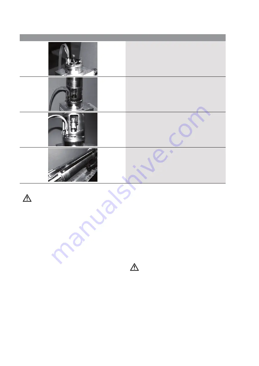
7.1.1 Assembly of motor and hydraulics
• Place the motor securely on a flat surface.
• Remove the plastic sleeve from the motor and attach the
connecting cable.
• Grease the motor shaft.
• Remove the cable protective cover for the hydraulics
• Place the motor and hydraulics together on one plane and
align so that the cable outlet on the motor is opposite the
cable guide on the hydraulics.
• Push the motor and hydraulics carefully together until the
toothing (spline shaft connections) of the shafts engage
with each other and the stud bolts pass through the flange
bores of the hydraulics.
• Screw the 4 locking nuts on to the stud bolts of the motor.
• Tighten the locking nuts crosswise (tightening torque
approximately 9 +/- 1 Nm)
• Lay the cable along the hydraulics and secure the cable
protective cover by tightening the 4 locking screws.
Содержание Wilo-Sub TWU 4 Series
Страница 4: ......


