21759-6-0608
Page 7
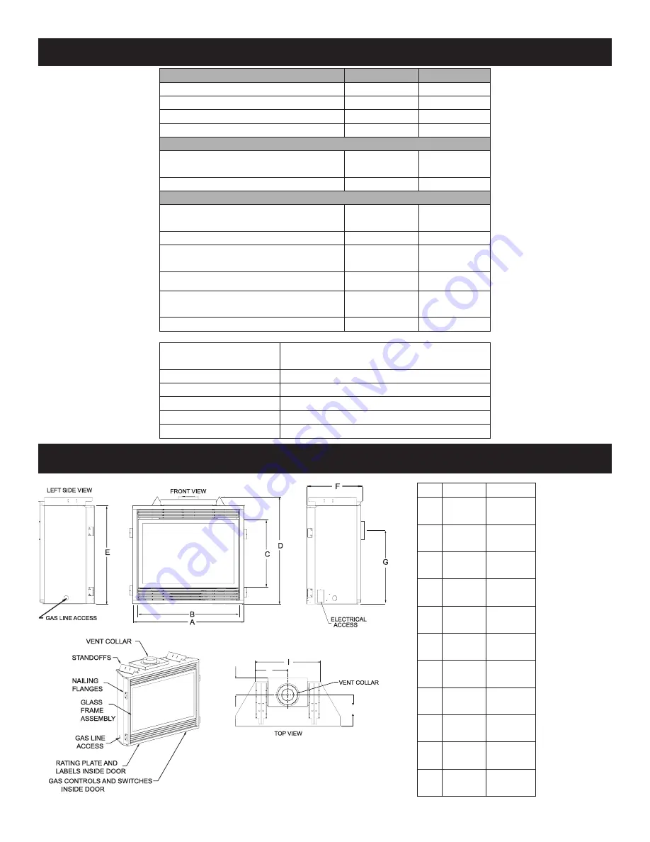
Figure 1
DVP42
DVP48
A
43"
1092mm
49"
1245mm
B
40"
1016mm
46"
1168mm
C
25 1/16"
636 mm
25 1/16"
636 mm
D
37 5/8"
956 mm
37 5/8"
956 mm
E
34 3/4"
883 mm
34 3/4"
883 mm
F
19 7/8"
505 mm
19 7/8"
505 mm
G
26"
660 mm
26"
660 mm
H
7 1/8"
181 mm
7 1/8"
181 mm
I
26 1/2"
826 mm
32 1/2"
826 mm
J
13 1/4"
337 mm
16 1/4"
413 mm
K
12 3/4"
324 mm
12 3/4"
324 mm
RIGHT SIDE VIEW
J
H
K
Remote Control Options
& Accessories
Description
FRBC
Millivolt Batt. Remote ON/OFF
FRBTC
Millivolt Batt. Remote T-Stat
TMW
Millivolt WIRELESS Wall Thermostat
TRW
Millivolt REED SWITCH Wall Thermostat
FWS-1
Direct Ignition/Millivolt Wall Switch
DVP42
DVP48
Input Btu/hr Maximum
28,000
30,000
Btu/hr Minimum (millivolt only)
19,000
20,500
KWH (Maximum)
8.2
8.8
(Minimum)
5.5
6.0
NAT.
Orifice
#38 (.1015)
P-203
#37 (.1040)
P-213
Air Shutter Opening
1/8"(3.2mm)
1/8"(3.2mm)
LP
Orifice
#52 (.0635")
P-213
1.65MM
P-250
Air Shutter Opening
FULL OPEN
FULL OPEN
Height without standoff
34 3/4"(3.2mm) 34
3/4"(3.2mm)
Width
43"(1092mm)
49"(1245mm)
Depth
19
7/8"(505mm)
19
7/8"(505mm)
Gas Inlet Shutoff Valve (Pipe)
1/2 NPT
1/2 NPT
NOTE:
Air shutter settings
are factory minimum
settings. Some venting
c o n f i g u r a t i o n s m a y
require minor air shutter
adjustments for optimum
performance.
SPECIFICATIONS
FIREPLACE DIMENSIONS
Содержание DVP42FP
Страница 48: ...21759 6 0608 Page 48 Figure 82 OPTIONAL THERMOSTAT OPTIONAL WALL SWITCH STANDING PILOT WIRING DIAGRAM ...
Страница 56: ...21759 6 0608 Page 56 INTERMITTENT PILOT TROUBLESHOOTING continued ...
Страница 60: ...21759 6 0608 Page 60 WIRING DIAGRAM WITH BLOWER Figure 85 RF WIRING DIAGRAM ...
Страница 71: ...21759 6 0608 Page 71 SERVICE NOTES ...


