21759-6-0608
Page 31
Follow correct option according to venting method.
Connecting Directly to Fireplace
If the air inlet and flue outlet tubes are to be connected directly to
the unit (no rigid venting system is being used), then the gasket
provided must be used to seal the 4” (102mm) flue outlet tube.
Peel the paper off the self-adhesive gasket and then wrap it around
the end of the tube (if tube was cut, it is recommended to use cut
end) as shown in Figure 48. Pull the gasket tight at all times while
wrapping it around tube. The gasket ends should align, to form a
complete seal. The overlapped section should NOT come in con-
tact with the seam in the tube. Apply high temperature sealant to
the opposite end of the tube (on the inside of the tube). The end
with the gasket will attach to the back of the unit. Continue with
Step 13.
Connecting to Rigid Vent System
If the air inlet and flue outlet tubes are to be connected to a rigid
venting system (and not directly to the back of the unit), then
do
not
use the gasket provided. High temperature sealant should be
applied to the outside of the 4” diameter (102mm) flue outlet tube
(if tube was cut, it is recommended to use cut end) and to the in-
side of the tube on the end that connects to the vent cap. Continue
with step 13.
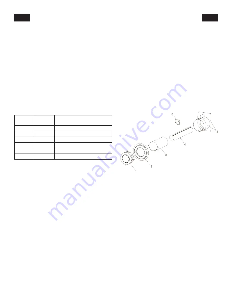
PARTS LIST
INDEX
NUMBER
PART
NUMBER
DESCRIPTION
1
DV769
Vent Cap Assembly
2
19193
Outside Mounting Plate
3
19194
Air Inlet Tube
4
DV524
Flue Outlet Tube
5
19196
Firestop/Thimble Assembly
6
20527
Gasket
Figure 49
DVVK-4RE VENT KIT INSTALLATION INSTRUCTIONS (cont.)
Содержание DVP42FP
Страница 48: ...21759 6 0608 Page 48 Figure 82 OPTIONAL THERMOSTAT OPTIONAL WALL SWITCH STANDING PILOT WIRING DIAGRAM ...
Страница 56: ...21759 6 0608 Page 56 INTERMITTENT PILOT TROUBLESHOOTING continued ...
Страница 60: ...21759 6 0608 Page 60 WIRING DIAGRAM WITH BLOWER Figure 85 RF WIRING DIAGRAM ...
Страница 71: ...21759 6 0608 Page 71 SERVICE NOTES ...


