


35
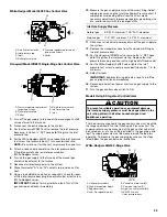
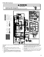
WFM18, WFD18 Wiring Diagram
Check codes for proper wiring and circuit protection before
installation.
NOTES:
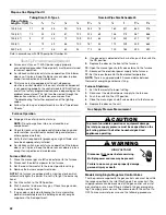
1. Set heat anticipator on room thermostat at 0.7 amps.
2. Manufacturer’s specified replacement parts must be used
when servicing.
3. If any of the original wire supplied with the furnace must be
replaced, it must be replaced with wiring material having a
temperature rating of at least 105ºC. Use copper conductors
only.
4. Blower speeds should be adjusted by the installer to match
the installation requirements to provide the correct heating
temperature rise and the correct cooling CFM. See the
specification sheet for the airflow chart.
5. Unit must be permanently grounded and conform to NEC and
local codes.
6. To recall the last 5 faults, most recent to least recent, depress
the switch for more than 2 seconds while in the standby
mode (no thermostat inputs).
HIGH VOLTAGE!
WARNING
Disconnect ALL power before servicing.
Multiple power sources may be present.
Failure to do so may cause property damage, personal injury or death.
Auto
1 Stg
150 Sec
5 Min 2
nd
Stg Delay
2 Stg Mode
100 Sec Heat Off Delay
Fuse
See Note 6
Integrated
Control Module
FS
1
2
3
4
5
6
7
8
9
10 11 12
BK
BK
BK
W
G
BK
W
BU
BR
OR
BR
Y
Y
Y
Y
R R
R
OR
BU
W
XFMR-H
LINE-H
EAC-H
PR
1
2
LINE NEUTRAL
HI HEAT-H
COOL-H
LO HEAT-H
PARK
Diagnostic
LED
BU
BR
W
BR
W (N)
BK (HI)
BU (MED)
OR (MED LO)
R (LO)
Auxiliary
Limits
PR
W
W
W
R
R
PR
PR
Hot
Surface
Igniter
2-Stage
Gas Control Valve
BR
BU
Y
Y
R
Primary Limit Switch
Door Switch
Located In Blower Compartment
On Some Models
Pressure Switch
NO
C
BK
W
W
W
BK
PM
1
C
2
HI
3
Burner Compartment
24 VAC
Humidifier
Blower Compartment
15-Pin Plug
On Some Models
Capacitor
Circulator
Blower
BR
XFMR
115V
24V
Humidifier
Integrated
Control Module
GND
XFMR (6)
GND (8)
MVC (9)
MVH (12)
MVL (2)
Gas
Control
Valve
Induced
Draft Blower
Pressure
Switch
C
NO
C
G
W
R
Auxiliary
Limit Controls
PS (10)
PS O (4)
HL I (7)
HL O (1)
To
Micro
Auto Reset
Primary
Limit Control
RO 2 (11)
RO 1 (5)
XFMR (3)
Manual Reset Rollout
Limit Control(s)
(Single Control On Some Models)
24 VAC
40 VA
Transformer
XFMR-N
115 VAC
24V Thermostat Connections
Circulator
Blower
Electronic
Air Cleaner
EAC-N
CIR-N
LINE-N
EAC-H
LINE-H
HI
HEAT-H
COOL-H
LO
HE
AT-H
Door
Switch
Junction Box
Disconnect
IND-N
IGN-N
IGN
IND
Induced
Draft
Blower
Integrated Control Module
Integrated Control Module
FP
XFMR-H
Hot Surface Igniter
Flame Sensor
1
2
3
4
C
0
5
6
7
8
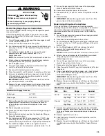
Steady On = Normal Operation
1 Flash = System Lockout (Retries/Recycles Exceeded)
2 Flashes = Pressure Switch Stuck Open
3 Flashes = Pressure Switch Stuck Open
4 Flashes = Open High Limit Switch
5 Flashes = Flame Sensed With Gas Control Valve De-energized
6 Flashes = Open Rollout Switch or Open Fuse
7 Flashes = Low Flame Signal
8 Flashes = Check Igniter or Improper Ground
Continuous Flashes = 115 VAC Polarity Reversed/Verify GND
Low Voltage (24V)
Low Voltage Field
High Voltage (115V)
Junction
Terminal
Internal To
Integrated Control
Plug Connection
Equipment GND
Field GND
Field Splice
Switch (Temp.)
Igniter
Pressure Switch
Overcurrent
Prot. Device
High Voltage Field
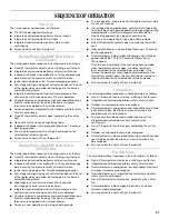
Gray
GY
White
W
Black
BK
Red
R
Blue
BU
Orange
OR
Yellow
Y
Green
G
Pink
PK
Azure
A
Violet
V
Brown
BR
Color Symbol
24 VAC
Humidifier
O
R
G
W
Y
Rollout Limit Switches
Single Control On Some Models
PR
Flame
Sensor
Induced Draft
Blower
To 115 VAC/1/60Hz Power Supply With
Overcurrent Protection Device
LINE-N
GND
LINE-H
Junction
Box
To 115 VAC/1/60Hz Power Supply With
Overcurrent Protection Device
N
L
GND
Y
0
Off = Control Failure


