


19
Contact your distributor for a tabular listing of appropriate
manufacturer’s kits for propane gas and/or high altitude
installations. The indicated kits must be used to ensure safe and
proper furnace operation. All conversions must be performed by
a qualified installer or service agency.
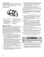
Gas Control Valve
This furnace is equipped with a 24-volt gas control valve
controlled during the furnace operation by the integrated control
module. As shipped, the gas control valve is configured for
Natural gas. The gas control valve is field convertible for use with
propane gas by replacing the regulator spring with a propane gas
spring from an appropriate manufacturer’s propane gas
conversion kit. Taps for measuring the gas supply pressure and
manifold pressure are provided on the valve.
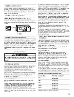
The gas control valve has a manual ON/OFF control located on
the gas control valve itself. This control may be set only to the
“ON” or “OFF” position.
Refer to the lighting instructions label or or see “Complete
Installation” for use of this control during start-up and shut down
periods.
Gas Piping Connections
When sizing a trunk line, be sure to include all appliances which
will operate simultaneously when sizing a trunk line. The gas
piping supplying the furnace must be properly sized based on the
gas flow required, specific gravity of the gas, and length of the
run. The gas line installation must comply with local codes, or in
their absence, with the latest edition of the National Fuel Gas
Code, NFPA 54/ANSI Z223.1.
Pressure 0.5 psig or less and pressure drop of 0.3" W.C.; Based
on 0.60 Specific Gravity Gas
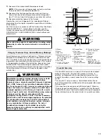
To connect the furnace to the building’s gas piping, the installer
must supply a ground joint union, drip leg, manual shutoff valve
and line and fittings to connect to the gas control valve. In some
cases, the installer may also need to supply a transition piece
from
¹⁄₂
" (1.3 cm) pipe to a larger pipe size.
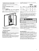
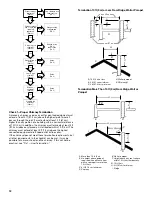
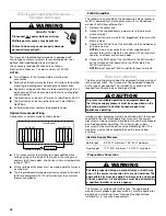
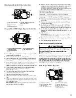
See “Gas Piping Connections” illustrations for typical gas line
connections to the furnace.
When connecting gas piping:
■
Use black iron or steel pipe and fittings for building piping.
■
Where possible, use new pipe that is properly chamfered,
reamed and free of burrs and chips.
NOTE: If old pipe is used, be sure it is clean and free of rust,
scale, burrs, chips and old pipe joint compound.
■
Use pipe joint compound (pipe dope) on male threads only.
■
Always use pipe joint compound (pipe dope) that is approved
for all gases.
■
Do not apply compound to the first 2 threads.
■
Use ground joint unions.
■
Install a drip leg to trap dirt and moisture before it can enter
the gas control valve. The drip leg must be a minimum of 3"
(7.6 cm) long.
■
Install a
¹⁄₈
" NPT pipe plug fitting, accessible for test gage
connection, immediately upstream of the gas supply
connection to the furnace.
■
Always use a backup wrench when making the connection to
the gas control valve to keep it from turning.
NOTE: The orientation of the gas control valve on the
manifold must be maintained as shipped from the factory.
■
Maximum torque for the gas control valve connection is
375 in/lbs.
NOTE: Do not overtighten the gas control valve.
■
Install a manual shutoff valve between the gas meter and the
furnace within 6 ft (1.8 m) of the furnace.
■
If a union is installed, the union must be downstream of the
manual shutoff valve, between the shutoff valve and the
furnace.
■
Tighten all joints securely.
■
Connect the furnace to the building piping by one of the
following methods:
1. Rigid metallic pipe and fittings.
2. Semirigid metallic tubing and metallic fittings.
NOTE: Aluminum alloy tubing must not be used in exterior
locations. In order to seal the grommet cabinet penetration,
rigid pipe must be used to reach the outside of the cabinet. A
semirigid connector to the gas piping may be used from
there.
■
Use listed gas appliance connectors in accordance with their
instructions.
■
Gas connectors must be fully in the same room as the
furnace.
■
Keep gas connectors and semirigid tubing away from
physical and thermal damage when installed.
■
Ensure aluminum alloy tubing and connectors are coated to
avoid external corrosion when in contact with masonry,
plaster or insulation, or subjected to repeated wetting by
liquids such as water (except rainwater), detergents, or
sewage.
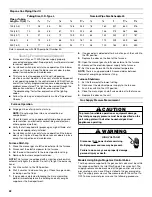
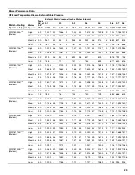
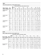
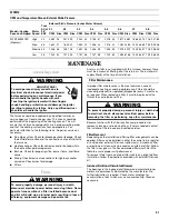
Natural Gas Capacity of Pipe—In cu ft (m
3
) of Gas Per Hour
(CFH)
Length
of
Pipe—
ft (m)
Nominal Black Pipe Size—inches
¹⁄₂
³⁄₄
1 1
¹⁄₄
1
¹⁄₂
10 (3)
132 (3.7) 278 (7.9) 520 (14.7) 1,050 (29.7) 1,600 (45.3)
20 (6.1)
92 (2.6)
190 (5.4) 350 (9.9)
730 (20.7)
1,100 (31.1)
30 (9.2)
73 (2.1)
152 (4.3) 285 (8.1)
590 (16.7)
980 (27.8)
40 (12.2) 63 (1.8)
130 (3.7) 245 (6.9)
500 (14.2)
760 (21.5)
50 (15.2) 56 (1.6)
115 (3.3) 215 (6.1)
440 (12.5)
670 (19)
60 (18.3) 50 (15.2) 105 (3)
195 (5.5)
400 (11.3)
610 (17.3)
70 (21.3) 46 (1.3)
96 (2.7)
180 (5.1)
370 (10.5)
560 (15.9)
80 (24.4) 43 (1.2)
90 (2.5)
170 (4.8)
350 (9.9)
530 (15)
90 (27.4) 40 (1.1)
84 (2.4)
160 (4.5)
320 (9.1)
490 (13.9)
100 (30.5) 38 (1.1)
79 (2.2)
150 (4.2)
305 (8.6)
460 (13)
Goodman 62
To avoid possible unsatisfactory operation or equipment
damage due to underfiring of equipment, use the proper
size of Natural/propane gas piping needed when running
pipe from the meter/tank to the furnace.
CAUTION
CFH =
Btu/h Furnace Input
Heating Value of Gas (Btu/cu. ft


