


14
In some cases, a shorter extension above the roof may be
possible with a liner than would be required with a masonry
chimney.
For further information on relining, see “Fix 4—Relining.”
Fix 2—Change Venting Arrangements
If the masonry chimney has more than one channel, it may be
possible to vent the gas appliances into one channel and vent the
solid or liquid fuel appliance(s) into another channel(s). Do not
vent an 80+ furnace inside of a metal liner with other appliances
vented outside the liner.
Alternatively, the homeowner may agree to discontinue use of the
fireplace (solid fuel appliance). If so, the tile liner must be cleaned
to remove creosote buildup. The fireplace opening must then be
permanently sealed.
If oil-fired appliance(s) are being replaced by gas-fired
appliance(s), the tile liner must first be cleaned to remove the fuel
oil residue.
If none of the above options is practical, the furnace may need to
be vented vertically with a B Vent.
Under some conditions, a 90%+ furnace could be installed rather
than an 80% furnace. The 90%+ furnace can be vented
horizontally or vertically through PVC pipe.
Fix 3—Rebuild the Crown
If the chimney crown is damaged, a qualified mason must repair
it in accordance with nationally recognized building codes or
standards. One such standard which may be referenced is the
Standard for Chimneys, Fireplaces, Vents, and Solid Fuel Burning
Appliances, ANSI/NFPA 211.
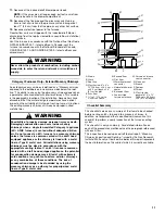
Fix 4—Relining
Relining options include B vent and flexible liners.
If the chimney has diagonal offsets, B vent probably cannot be
used.
If B vent is to be used, it must be supported adequately.
Supports (such as fire stops or thimbles) must be used to keep
the B vent from coming into direct contact with the tile liner or
chimney walls. Direct contact would result in higher heat loss,
with an increased possibility of poor venting system
performance.
It is not acceptable to vent one appliance inside the B vent and
other appliances outside.
The excess space between the B vent and the chimney walls
must be covered at the top of the chimney by a weatherproof,
corrosion resistant flashing. The B vent should then be topped
with a listed vent cap. The listed vent cap will, when installed
according to the manufacturer’s instructions, prevent problems
due to rain, birds or wind effects.
A B vent installed as described in this section is considered to be
an enclosed vent system, and the sizing tables in National Fuel
Gas Code NFPA 54/ANSI Z223.1—latest edition and in the
National Standard of Canada, CAN/CSA B149.1 and CAN/CSA
B149.2—latest editions and amendments may be used.
If a flexible liner is to be used, it must be made of the proper
materials, such as:
■
For most residential applications, an aluminum liner should
be acceptable.
■
If the combustion air supplied to the furnace will be
contaminated with compounds containing chlorine or
fluorine, a liner of AL 29-4C stainless steel should be used.
Common sources of chlorine and fluorine compounds include
indoor swimming pools and chlorine bleaches, paint
strippers, adhesives, paints, varnishes, sealers, waxes (which
are not yet dried) and solvents used during construction and
remodeling. Various commercial and industrial processes
may also be sources of chlorine/fluorine compounds.
■
Heavier gauge 300 and 400 series stainless steel liners were
developed for use with oil or solid fuel appliances. They are
not suitable for use with gas-fired appliances. Flexible liners
specifically intended and tested for gas applications are listed
in the UL “Gas and Oil Equipment Directory” (UL Standard
1777).
For sizing of flexible liners, see Note 22 and the tables in the
National Fuel Gas Code NFPA 54/ANSI Z223.1—latest edition
and in the National Standard of Canada, CAN/CSA B149.1 and
CAN/ CSA B149.2—latest editions and amendments.
To install the liner, read and follow the liner manufacturer’s
instructions and your local codes. Excess liner length should be
pulled out of the chimney and cut off.
NOTES:
■
Use caution when doing this, as the cut edges of flexible
liners may be sharp.
■
Do not spiral excess liner inside of the chimney.
■
Support the liner as recommended by the liner manufacturer.
Some manufacturers of flexible liners offer an insulation sleeve
designed to be added to the liner before it is installed in the
chimney.
NOTE: Poured insulation, either vermiculite or other materials, is
no longer recommended.
Insulation will need to be added to the flexible liner if:
■
It is required by the liner manufacturer’s instructions.
■
The previous liner was properly sized and installed, and
suffered from condensation damage.
■
It is required by your local building codes.
Even if none of the 3 conditions exist which require additional
liner insulation, the installer may wish to consider installing
additional insulation if:
■
The local climate is very cold.
■
The chimney is very tall.
■
The vent connectors used are very long or have a large
number of elbows.
■
Local experience indicates that flexible liners installed without
insulation are likely to have condensation problems.
Insulation must be selected and installed in accordance with the
liner manufacturer’s instructions.
Finally, cap the chimney and terminate the liner in accordance
with the liner manufacturer’s instructions.
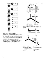
Install Ductwork
IMPORTANT:
■
Install ductwork in accordance with NFPA 90B and any local
codes.
■
When the furnace is installed so that the supply ducts carry
air circulated by the furnace to areas outside the space
containing the furnace, the return air shall be handled by a
duct or ducts sealed to the furnace casing and terminated
outsides the space containing the furnace.
■
If there is no complete return air duct system, the return air
connection must be sealed to the furnace casing and run full
size to a location outside the utility room or space housing
the furnace to avoid a negative pressure on the venting
system.


