


32
Flame Sensor (Qualified Servicer Only)
Under some conditions, the fuel or air supply can create a nearly
invisible coating on the flame sensor. This coating acts as an
insulator causing a drop in the flame sense signal. If the flame
sense signal drops too low the furnace will not sense flame and
will lock out. The flame sensor should be cleaned by a qualified
servicer using emery cloth or steel wool. Following cleaning, the
flame sense signal should be 1 to 6 microamps at 115 volts.
Burners
Visually inspect the burner flames periodically during the heating
season. Turn on the furnace at the thermostat and allow several
minutes for flames to stabilize, since any dislodged dust will alter
the flames normal appearance. Flames should be stable, quiet,
soft, and blue (dust may cause orange tips but they must not be
yellow). They should extend directly outward from the burners
ports without curling, floating, or lifting off of the ports. Flames
must not impinge on the sides of the heat exchanger firing tubes.
Cleaning (Qualified Servicer Only)
1. Disconnect power and turn off the gas supply to the furnace.
2. Disconnect the rollout limit wires, flame sensor wire and the
igniter plug.
3. Remove the 4 screws securing the burner box top.
4. Remove the screws securing the burners to the burner
bracket. Remove the burners.
5. Use a bottle brush to clean the burner insert and the inside of
the burner.
6. Replace the burner (opposite of removal). Check tha tthe
burners are fully seated on the burner bracket and are
properly aligned.
7. Replace burner box top.
8. Reconnect wiring.
9. Reconnect power and the gas supply to the furnace.
10. Check the furnace for proper operation. See “Operational
Checks” to verify the burner flame characteristics.
TROUBLESHOOTING
See “Electrostatic Discharge (ESD)” before touching any
electronic part on this furnace.
Furnace Fails to Operate Properly
Review “Sequence of Operation” and visually inspect the
following before troubleshooting:
■
Is the integrated ignition/blower control board and power to
the furnace on?
■
Is the blower compartment door securely closed?
■
Are the manual shutoff valves in the gas line to the furnace
open?
■
Are all wiring connections secure?
Start the system by setting thermostat above room temperature.
Observe system response. Then use the information provided in
this section to check the system operation.
Fault Recall
The ignition control is equipped with a momentarty pushbutton
switch that can be used to display the last 5 faults detected by
the control on the diagnostic LED. The control must be in
Standby Mode (no thermostat inputs) to use the feature. Depress
the pushbutton switch for approximately 2 seconds. Release the
switch when the LED is turned off. The diagnostic LED will then
display the flash codes associated with the last 5 detected faults.
The order of display is the most recent fault to the least recent
fault.
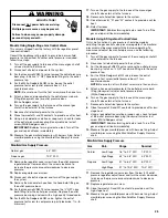
Goodman 73
To avoid property damage, personal injury or death due
to fire, do not remove any internal compartment covers
or attempt any adjustment. Electrical components are
contained in both compartments. Contact a qualified
service agent at once if an abnormal flame appears.
WARNING
Goodman 59
Label all wires prior to disconnection when servicing
controls. Wiring errors can cause improper and dangerous
operation. Verify proper operation after servicing.
CAUTION
Goodman 77
The igniter is fragile and can be easily damaged. Use
extreme caution when removing the burner box cover.
CAUTION
Goodman 59
Label all wires prior to disconnection when servicing
controls. Wiring errors can cause improper and dangerous
operation. Verify proper operation after servicing.
CAUTION
Goodman 6
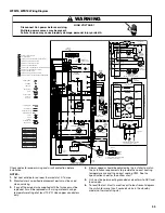
HIGH VOLTAGE!
WARNING
Disconnect ALL power before servicing.
Multiple power sources may be present.
Failure to do so may cause property damage,
personal injury or death.


