2-13
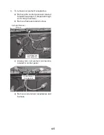
2. Use Phillips screwdriver to remove the
ground-link screw from the back of the
range. Save the ground link screw and
discard the remaining end of the ground
link.
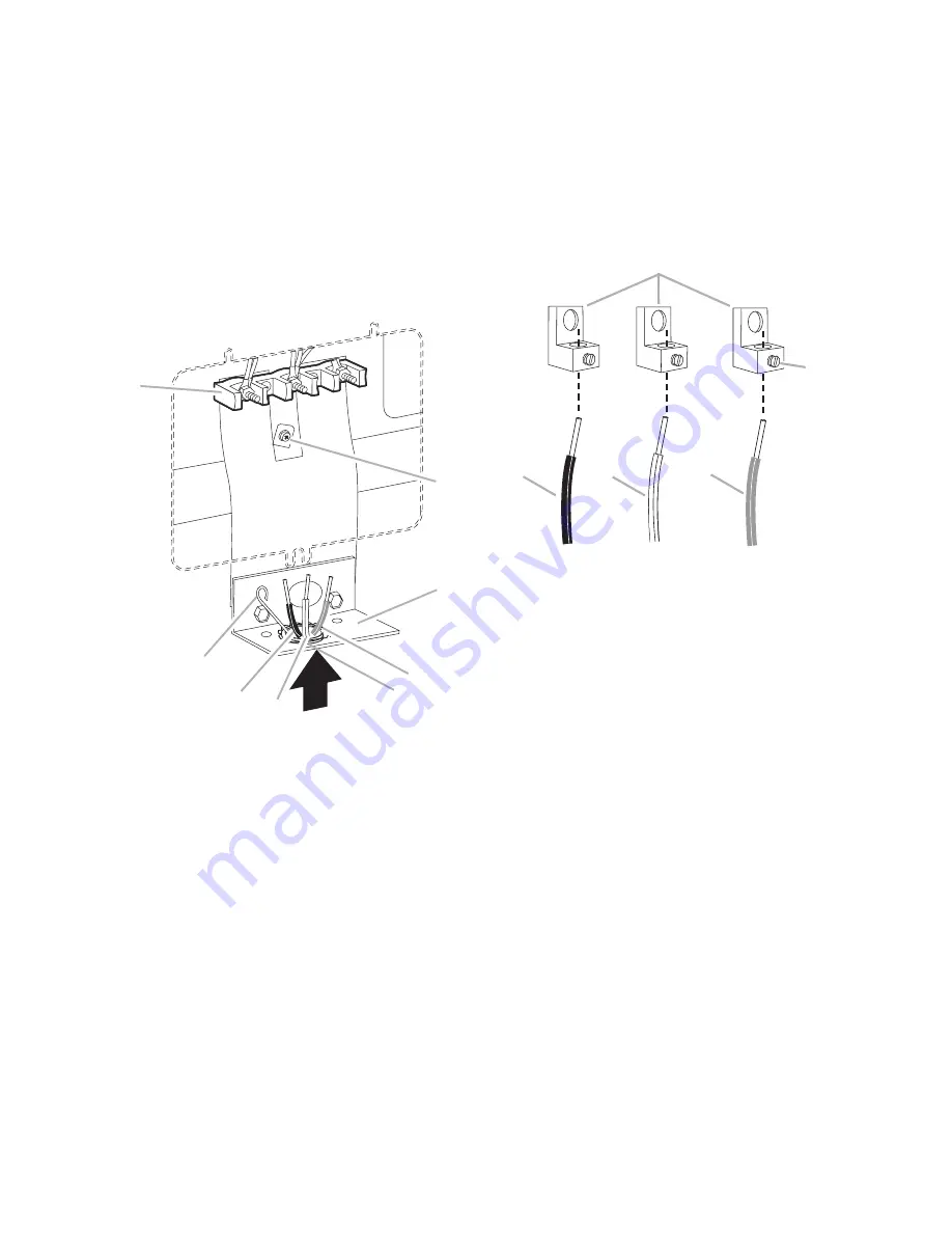
3. Pull the conduit through the strain relief
on cord/conduit plate on bottom of range.
Allow enough slack to easily attach wiring
to the terminal block.
A. Terminal block
B. Ground-link screw
C. Cord/conduit plate
D. Line 2 (red) wire
E. Neutral (white) wire
F. Line 1 (black) wire
G. Bare (green) ground wire
H. Strain Relief
A
B
C
D
E
F
G
H
4. Attach terminal lugs to line 1 (black), neutral
(white), and line 2 (red) wires. Loosen (do
not remove) the set screw on the front of the
terminal lug and insert exposed wire end
through bottom of terminal lugs. Securely
tighten set screw to 10 lbs in. torque. See
Bare Wire Torque Specifications chart.
A. Terminal lug
B. Set screw
C. Line 1 (black) wire
D. Neutral (white) wire
E. Line 2 (red) wire
A
B
C
D
E
Содержание RY160LXTQ
Страница 26: ...2 18 NOTES ...
Страница 52: ...5 6 NOTES ...
Страница 58: ...6 6 NOTES ...
Страница 59: ...7 1 WIRING DIAGRAMS ...
Страница 60: ...7 2 ...
Страница 62: ......


