SECG 4.0 | User Manual
WHALETEQ
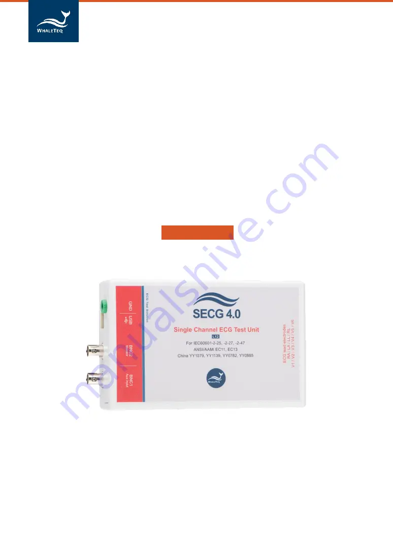
Single Channel ECG Test System
(SECG 4.0)
User Manual
(Revision 2020-12-31)
Страница 1: ...SECG 4 0 User Manual WHALETEQ Single Channel ECG Test System SECG 4 0 User Manual Revision 2020 12 31 ...
Страница 2: ... 2 6 1 Main function main waveform 18 2 6 2 DC offset setting 20 2 6 3 Input impedance test 20 2 6 4 Output lead electrode 20 2 6 5 Lead electrode impedance 21 2 6 6 Pacing parameters 21 2 6 7 Output graphic display 22 2 6 8 Special functions 23 2 6 9 Auto Pacing Auto Heart Rate Calibration Mode 24 2 6 10 Load ECG File 25 2 7 Software Options SECG Assistant 26 2 7 1 Activate the SECG Assistant Sof...
Страница 3: ...5mV level 10mVpp The SECG 4 0 contains resistor capacitor networks dc offset pacing circuit and relay switching to provide the full range of single channel performance tests in IEC YY JJG standards as described in Section 1 2 The basic range of tests in the standards include for example Sensitivity accuracy of the mV mm indication Frequency response sine wave and impulse tests Input impedance Nois...
Страница 4: ...waveforms are alternates For two tests may be required 201 12 4 102 3 test of lead networks and 201 12 4 105 3 test of ringing from mains notch filter For 201 12 4 101 large dc offset test the SECG is limited to 1Vdc However this is almost certainly enough to exceed the point of saturation For the test circuit in figure 201 110 switch position A is not provided This is considered an error in the s...
Страница 5: ...erformance tests except CMRR and as noted left See below for Clauses 5 1 4 n and 5 2 9 1 f g 1 General limitation this equipment is designed for use with isolated ECG circuits as are generally provided for medical ECG If applied to a non isolated circuit the noise may be excessive 1 5 1 4 n Fast QRS The sampling rate is limited to 0 2ms some distortion of the pulse is possible below 6ms 5 2 9 1 f ...
Страница 6: ...stem inside the SECG 4 0 module BNC1 BNC2 Additional input to allow connection to an external function generator e g analogue type if aliasing is suspected Precision divider ensures that 1V in 1mV out 0 2 Connects to the PC via USB 2 0 For noise reduction Allows monitoring of the applied signal pre divider 1V 1mV output ...
Страница 7: ...t range is used Frequency pulse repetition rate accuracy 1 0 1 Pulse duration timing accuracy excluding pacing 1ms 0 2ms Pacing pulse width accuracy 5µs 1µs Pacing pulse amplitude accuracy range 2mV pulse 1 2mV pulse 10 Range 2mV to 700mV 2mV pulse 0 3 100mV pulse 1 or 5mV Pacing pulse characteristics Rise fall time 5µs Overshoot 1 Settling time 1 Pacing pulse overshoot intentional Method A accord...
Страница 8: ...tion IC as well as special filters to reduce noise from microprocessor 8MHz and DC DC converter 200kHz 1 5 Cautions Before using products use a grounded wrist strap or touch a grounded safely object or a metal object such as the power supply case to avoid damaging them due to static electricity WhaleTeq does not recommend to connect test equipment with DUT to conduct Electrostatic Discharge ESD te...
Страница 9: ... the destination folder and make sure the all files are unzipped in the same folder Double click on the SingleChannelECG exe to execute the SECG4 0 program If SECG software can t be executed properly or this is the first time using WhaleTeq product please refer to below two sections to confirm that USB driver and Microsoft Net Framework 4 0 are all installed 2 Relative to normal PC processing ther...
Страница 10: ...rcement in Windows 8 and Windows 8 1 Please click here to watch the tutorial video When the USB module is connected for the first time select manual installation and point to the folder containing the above file Then continue to follow the instructions to finish the installation There may be a warning that the driver is not recognized by Windows and this can be ignored Please click here to watch t...
Страница 11: ... box includes 1 RA V6 terminals Total 10 terminals corresponding to the 10 electrodes of 12 lead ECG or fewer lead channel ECG 2 GND terminal The terminal connected to ground 3 CMRR Imbalance with DC The terminal is only used with CMRR 2 0 for CMRR testing purpose Alternately the ECG device under test can be directly connected to the USB module using a male D15 connector The pin outs are 1 RA 4 RL...
Страница 12: ...tisfactory without any special efforts However for the input impedance test with the 620kΩ is in series the imbalance in impedance can cause high noise For this test the ac filter may be turned on If the noise is still excessive move to an electrically quiet environment or increase the size of the metal sheet underneath and around the set up Frame ground or EP terminal Metal bench metal sheet or f...
Страница 13: ...are update has been supported from March 2017 If your SECG 4 0 doesn t support the feature please contact WhaleTeq for upgrade at service whaleteq com Question How to check your SECG 4 0 have supported Firmware Update Answer Connect the SECG 4 0 device to PC Go to About dialog then check whether the F W Version and H W Version buttons are hidden Please watch Step 1 in below section for where to fi...
Страница 14: ...ring the Firmware Update period 2 4 1 How to update Firmware If your SECG 4 0 support Firmware Update feature Below is the step by step instruction for how to update firmware Step 1 Connect the SECG 4 0 device to PC then open SECG application with version 5 0 0 6 or higher Move the cursor to System Menu Bar right click your mouse Then there will show up a menu select About ...
Страница 15: ... 3 Go to WhaleTeq website reference below table to download compatible Firmware file Hardware Version Firmware Version 2 7 4 4 or above 2 8 or above 5 5 or above Step 4 Back to SECG application select the downloaded firmware file Step 5 The application will show an information dialog After pressing OK the operation cannot be cancelled ...
Страница 16: ...16 Single Channel ECG Test System User Manual Step 6 Wait for firmware update complete Step 7 Please restart the SECG system to complete firmware update process 2 5 Main Screen ...
Страница 17: ...nce for standard performance tests SECG Assistant is for IEC and SECG Assistant II is for YY and JJG China standard 08 Pulse Waveforms Select the pulse waveform type Pulse Width is a related parameter 09 Input Impedance Test Selects if 620kΩ 4 7nF is in circuit for input impedance test 10 ECG 2 27 A special waveform related to the ECG waveform IEC 60601 2 27 QRS Duration and T Wave are the paramet...
Страница 18: ...mVpp and frequency Hz or bpm Rectangle pulse A rectangular pulse according to the amplitude setting pulse width ms and pulse repetition rate frequency Hz or bpm Triangle pulse A triangle pulse according to the amplitude setting base pulse width ms and pulse repetition rate frequency Hz or bpm Exponential Exponential waveform used to Hysteresis test according to the amplitude mVpp and frequency Hz ...
Страница 19: ...s the setting matches the base of the triangle pulse For exponential pulse the set pulse width is time constant Pulse width can be set to down to 2ms4 QRS Duration Allows the setting of the QRS component of the ECG wave in IEC 60601 2 27 in the range of 10 to 120ms matching the requirements of the standard5 T Wave allows setting of the amplitude of the T Wave in ECG waveforms to verify tall T wave...
Страница 20: ...laces the 300mV offset in series with the RL N as per IEC 60601 2 25 switch position C in Figure 201 110 2 6 3 Input impedance test This check box allows the user to switch in an impedance of 620kΩ 4 7nF in series with the main function for testing the input impedance of the ECG device under test When the check box is ticked the impedance is shorted The 300mVdc offset can be used in conjunction wi...
Страница 21: ...ardless of other pacemaker settings When set at 2 or 2mV the pacing pulse comes from the main 1000 1 divider which is accurate to better than 1 For settings above 2mV the output comes from Ch2 which has a design accuracy of 1 or 5mV Pacing Duration Can be set between 0 1 and 2 0ms covering the range required by all standards Overshoot Time Constant Settings from 2ms to 100ms creates an overshoot a...
Страница 22: ... display provides an image similar to that provided by ECGs The sensitivity of the display range may be set at 4mm mV 10mm mV or 20mm mV to cover the full range of waveforms offered by the system The time rate is fixed The output display uses the same data as used in the DAC output and serves as a cross check of the selected waveform and also allows the user to view the original waveform as filter...
Страница 23: ...tended for testing ECGs AAMI EC 13 Drift test ECG 2 27 waveform only when checked adds 4mVpp 0 1Hz triangle waveform to the ECG signal for testing baseline drift Dynamic Range Test square wave only when checked adds a 1mVpp waveform at the frequency indicated 20 30 or 40Hz intended for combination with an adjustable square wave for testing Clause 51 107 2 in IEC 60601 2 51 Frequency scans Sine may...
Страница 24: ...the tests can be grouped into synchronized heart rate and pacing is 60bpm and asynchronous heart rate 30 bpm pacing 80 bpm In addition 2mV pacing pulse uses a separate range Changing to this range can cause switching transients that can affect the heart rate Therefore separately out testing for 2mV is recommended Based on experience it is recommended to have a change interval of at least 30s With ...
Страница 25: ...pports two formats Text and Binary files Text txt Ascii file Windows line breaks LF CF first line is sample rate Hz second line number of samples following lines are samples in microvolts one sample per line Binary files bin Bytes 1 2 are sample rate Hz Bytes 3 6 are number of samples Following bytes are samples 2 bytes per sample all data is bigendian high byte first 2 s compliment The maximum si...
Страница 26: ... 2013 JJG760 2003 with detailed preset parameter settings and actual test sequence for testing needs 2 7 1 Activate the SECG Assistant Software Once you have installed the SECG4 0 you may also activate your purchased SECG Assistant Software Please connect SECG to your computer then follow the two steps below to activate your SECG Assistant Software First click on the SECG Assistant bottom to launc...
Страница 27: ... Step 1 Copy the Hardware ID SECG Device ID and send it to service whaleteq com to request an Active Key Step 2 A unique Active Key will be send to you via email Enter the Active Key and click the Active button Your SECG Assistant is now activated ...
Страница 28: ...mputer License is bound with SECG 4 0 If you would like to change the License bound way from computer to SECG 4 0 contact Whaleteq for upgrade your SECG 4 0 at service whaleteq com 2 7 2 SECG Assistant Operation Step 1 Click the SECG Assistant button to initiate the SECG Assistant software from the main screen The first thing you will see is that we have pre programmed all the test clauses require...
Страница 29: ... test your ECG Choose the specific test clause you needed the Goldberger and Wilson leads is used as an example Step 3 After you have selected the specific test clause you can see that all necessary parameters have been pre programmed for that clause Choose the desired setting under Parameter Settings to proceed ...
Страница 30: ...on for further measurement references Step 5 Click RUN to execute the test per your specified settings A new window will pop up to display the crucial information about your test such as parameter settings and pass criterion for your confirmation All other settings will be set by the SECG Assistant per specific standard requirements ...
Страница 31: ... You may view the actual execution sequence by clicking Test Sequence This will open another window display the details of each test steps for your engineering needs Step 7 When you have completed testing click Finish and proceed to the next desired test ...
Страница 32: ... and terminals referred to in the three IEC ECG related standards the intended function and settings in WhaleTeq s Single Channel ECG 2 25 Figure106 2 27 Figure105 2 47 Figure101 Function WhaleTeq SECG Settings S2 S S2 Connects the function generator to the ECG Automatically connected when function is selected S5 S1 None Shorts out the 100kΩ allows large signals The SECG automatically selects Ch1 ...
Страница 33: ...e LEAD V1 involves V1 RA LA LL but not V2 V6 The interpretation could be then that V1 should be connected to P1 with RA LA and LL to P2 and V2 V6 are connected to terminal P6 along with RL N A more reasonable interpretation would be to follow the diagram and test each LEAD wire in turn first RA then LA LL V1 etc with all unused LEAD wires connected to P2 Similarly the test for multichannel crossta...
Страница 34: ...Main Functions see 2 6 1 These waveforms have been obtained from the Physionet website 6 8 2 bb 5 Response time to a change in heart rate The results of this test can occasionally be on the limit It is possible to have time delays of up to 1s between changing the rate on the PC and the actual output as the WhaleTeq system implement changes only at the end of a cycle to ensure a smooth transition I...
Страница 35: ...values For this reason a wide filter diagnostic is recommended for which set values should match displayed values The test for sensitivity must be performed with the 1mVpp 20Hz sine wave easy to overlook as the previous test used a triangle wave Patient monitors with a monitor filter setting may have some reduction or variation at 20Hz due to the filter s characteristics rather than any measuremen...
Страница 36: ...surement time base settings should be adjusted to suit the frequency e g use 12 5mm s for 0 67Hz and 50mm s for 40Hz 50 102 4 Input noise For this test the USB module can be disconnected from the PC to eliminate any possible noise source In the unpowered condition all inputs are connected to RL N through 51kΩ 47nF resistors are required by the standard Measurement of noise using printouts or scree...
Страница 37: ... page folds so it is important to test using the 25Hz waveform in the standard However for testing the screen it may be that the width of line prevents individual lines from being seen clearly The nature of the screen is such that variations are not expected so a test at 1Hz e g a 100ms rectangle pulse with a frequency of 1Hz may be sufficient to measure the actual time base Alternately reduce the...
Страница 38: ...assist in determining compliance 50 102 9 Calibration voltage The standard appears to require a calibration voltage but in the last sentence provides an exception for patient monitors that provide a gain indication Virtually all patient monitors use this exception making the clause not applicable 50 102 10 Common mode rejection ratio Test requires a separate box available from WhaleTeq 50 102 11 B...
Страница 39: ...eters 50 102 13 Rejection of pacemaker pulses Again this test may require special settings in the patient monitor There are a large amount of combinations required for this test An Auto Pacing function see 2 6 9 has been provided to reduce operator time in testing However some experimentation is recommended to decide on groups of settings which suit the patient monitor Settings associated with the...
Страница 40: ... 0bpm is infinitely long As for 50 102 13 there are a large amount of combinations required for the main rate test An Auto Heart Rate function see 2 6 9 has been provided to reduce operator time in testing It is recommended to use only one heart rate and vary the other settings amplitude and QRS duration It should be noted that main difficult of the patient monitor will be at the lowest amplitudes...
Страница 41: ...t the patient monitor shows the correct heart rate in the presence of a high T wave At some point most patient monitors will treat the high T wave as new QRS pulse and hence double count the heart rate e g display 160bpm for an 80bpm input Note a T wave of 1mV will actually appear higher than the QRS with an amplitude of 1mV due to the characteristics of Figure 119 Note In the future it is planned...
Страница 42: ...validation including software A report for this can be provided on request Prior to shipping each unit is tested for component values and output voltages using a calibrated precision multi meter As WhaleTeq cannot provide ISO 17025 accredited calibration laboratories which are required to follow ISO 17025 should perform calibration either periodically or on a before use basis following normal proc...
Страница 43: ...ence and explanation The calibration mode does not include pacemaker rise time which is included in the manual procedure here Calibration procedure Parameter Nominal value tolerance Method RL N resistance 51kΩ 1 The 51kΩ can be measured between any lead electrodes and RL N terminals Note the resistors used are usually accurate to 0 1 but the measured value will be closer to 51 22kΩdue to the inclu...
Страница 44: ... Fluke 8845A or equivalent precision meter measure and record the peak to peak voltage at BNC2 by zeroing during the negative cycle and measuring at the positive cycle nominally 10Vpp Repeat this measurement at the output between RA and LL nominally 10mV Calculate the ratio and confirm it is 1000 1 0 2 Output voltage Setting 1 Method Set up 0 5mVpp 0 1Hz square wave output to RA Measure the peak t...
Страница 45: ... wave Measure the frequency at BNC2 using any appropriate meter Note this verifies the system clock is accurate Verification of other frequencies or timing is not as this is covered by software validation although users are free to measure other frequencies and timing The use of 40Hz is recommended to avoid beating with mains frequency Pacemaker pulse characteristics Voltage 10 pulse width 1 rise ...
Страница 46: ... USB module reconnect the USB module and re start the USB module 7 Purchasing Information 7 1 Standard accessories SECG 4 0 x 1 SECG 4 0 software CD x 1 12 lead breakout box x 1 Compound Terminal x 12 USB cable x 1 Grounding cable x 1 7 2 Optional Software and accessories SECG Standard assistant software IEC 60601 2 25 2011 SECG Standard assistant software IEC 60601 2 27 2011 SECG Standard assista...
Страница 47: ...Version Modify Content Issue Date 20201231 Add Chap 4 Software Development Kit SDK Chap 7 Purchasing information Chap 8 Version information 2020 12 31 9 Contact Details WHALETEQ Co LTD service whaleteq com O 886 2 2596 0701 9F No 27 Minquan W Rd Taipei City 10452 Taiwan ...