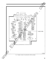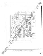
mately 0. 1 V less than voltage measured in
section a.
6. Apply twice tap value ac current.
a. Apply rated relay vo ltage. Voltage at
TP3 = 1 2.7V. Voltage at TP4 = less than
0.5V.
b. Interrupt ac current. Voltage at TP3 = less
than 0.5V. Voltage at TP4 = 1 2.7V.
7 . Apply rated voltage to relay terminal 18 (52 a
input) .
a . Apply rated relay voltage to terminal 9 .
Voltage a t TP4 = less than 0.5V.
b. Reduce voltage to terminal 18 to 60% of
0
rated relay voltage. Voltage at TP4 = 1 2 .7V.
8 . Jumper test point TP6 and TP7. Apply twice
tap value ac current.
a. Apply rated relay voltage. Voltage at
TP5 = 6.2V.
b . Remove j umper . Apply rated voltage.
Voltage at TP5 = less than 0.5V.
9. J urn per test point TP6 and TP7 .
a. Apply rated relay voltage. Voltage at printed
circuit board terminal I 0 or 1 1 = less than
0.5V (X and AR relay picked up).
b. Rem ove j u m per . A pply rated voltage.
Voltage at pc terminal 1 0 = 24V (X relay not
picked up). Voltage at pc terminal I I = rated
relay voltage (A R relay not picked up).
Overcurrent Module
0
1 . Jumper test points TP6 and TP7 (timer module).
Set tap in 0 . 5 hole and turn tap multiplier knob
to X 1 position .
a . Apply 0.5 a m p a c current t o the particular
input in question. Then apply rated relay
voltage. M easure 6.6 Vac at the transformer
secondary terminals. The same voltage
sh ould be read with the tap in the 1 .5 amp
tap and 1 . 5 amps ac applied. Likewise with
the 4.5 amp tap.
2 . Jumper test points TP6 and TP7 . Set tap in 0.5
0
amp. hole and turn tap multiplier to X 1 posi
tion .
I. L. 41-776.5A
a. With 0.4 amp ac current flowing apply rated
relay voltage. Measure voltage at terminal 5
of I C I to be 6.4V. N ow increase the current
until the output relay operates. The voltage
sh ould now read approx. 5 .4V. At this point
the voltage at terminal 4 should measure
6.4V. The voltage at printed circuit board
terminal 3 should measure 23.5Vdc before
the output relay operates and less than 2.5V
after it operates.
3 . Jumper test points TP6 and TP7. Set tap in 0.5
hole and turn tap multiplier knob fully CW.
a. Apply 0.5 amp ac and apply rated relay
voltage. M easure 4.2 volts at the brush ter
minal of the tap multiplier rheostat.
4 . J u mper test points TP6 and TP7 (timer
module).
a. Apply rated relay voltage. M easure 6.2V at
TP I and less than 0.5V at TP2.
b. Remove jumper. Apply rated relay voltage.
Measure less the 0.5V at TP l and 24V at
TP2.
5 . Check of Reed relay ( R R) contact.
a. Resistance should be greater than 500 ohms
when measured from jumper J
I
to com mon
negative.
b. Jumper test points TP6 and TP7 and apply
rated relay voltage. Resistance should drop
to less than 5 ohms.
6. Check coil resistance of reed relay (RR) ( 1 000
ohms), A R relay (630 ohms) and X telephone
relay ( 1 500 ohms). Attention should be paid to
polarity since each of the coils have a diode con
nected across it.
R E N EWAL PARTS
Repair work can be done most satisfactorily
at the factory. H owever, interchangeable parts
can be furnished to the customers who are equip
ped fo r doing the repair work. When ordering
parts, always give the complete nameplate data,
and style numbers from the electrical parts list.
9
www
. ElectricalPartManuals
. com

