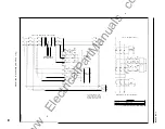
The same procedure should be fol lowed for the
ground overcurrent circuit as was used for phase A
input.
Remove jum per from TP6 and TP7 on the
timer m odule.
Control Timer
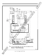
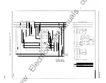
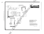
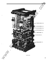
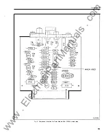
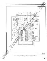
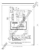
Refer to Fig. 4 and 5 or 6 when repl acing com
ponents.
If components in the control timer circuit have
been replaced or if it is desired to change the con
trol timer setting the same procedure should be
used as described under acceptance test ing.
Breaker Failure ( BF} Timer
If the scale appears to
be
o ff calibru tion due
to
slippage of the knob pointer on the shaft, this can
be corrected by rotating the shaft fully
CCW.
N ow
adjust the k n ob at the pin prick mark . This should
return the k n ob to its original position on the sha ft
and bring the scale markings back i nto calibration .
i f
components in the breaker failure timer cir
cuit have been replaced
it
may be necessary to
change the scale plate and recalibrate .
First
jumper test points TP6 and TP7. Using
a l cnv
bounce initiate switch adjust timer k nob until
a
25
ms time delay has been obtained . U se test
procedure described under acceptance testing for
measuring time delay. N ote the knob position for
25 ms delay . Also note the k nob position for 1 75
ms delay . Loosen the set screw and position the
k nob on the shaft so that the 25 and 1 75 ms
locations are equidistant about the knob locking
tab. Scribe lines at the 25 ms setting and for each
25 ms increment up to 1 75 ms.
Indicating Contactor Switch ( I CS)
Adjust the contact gap for approximately
. 047" by adjusting the stationary contacts. Both
contacts should make simultaneously.
Check to see that the contacts close at rated
tap va lue current. The indicating target should
drop at or just prior to the contacts closing. The
targer should drop freely.
I f the target does not drop or does n ot reset it
may be necessary to remove the cover and bend the
8
tab on the spring that supports
the
target.
T R O U B L E S H O OTI N G
The components i n the S B F- 1 relay are
operated wel l within their rating and normally will
give l ong and trouble free service. H owever,
if
a
relay gives indication of trouble in service or dur
ing routine checks the fo ll owing informati on will
prove helpful. All measurements are approximate
a nd may vary as much as 20%. All voltages ar�;
p•Jsitive with reference to common negative ( reluy
term inal 8 ) except ac voltages .
Timer Module
l . Jumper
test
points TP6 and
TP7.
a . Apply rated relay voltage. Voltage
at
l ower
test j ack = 23 . 5 V
b . Rem ove jumper. Apply rated voltage .
Voltage at l ower test jack = 2 3 . 5
c::c.
1
Jumper test poi nts
TP6 and
TD7
:1 .
Apply rated relay voltage. Voltage
at
u oper
test jack = !es'i than 2 . 5
Ydc:.
h.
Rem ove jumper. A pply r:J�ed vollage .
Voltage at upper test jack = less t h a n
2 . 5
Vdc .
3 .
jumper test points TP6
and "':P7.
a. Apply rated voltage. Voltage at
term inal 6
of l e i = l 8 . 3 V .
b. Rem ove jumper. Apply rated voltage.
Voltage at terminal 6 o f
I
C I should be ap
proxim ately 0. 1 Vdc less than voltage
measured in section a.
4. Jumper test points TP6 and TP7.
a. Apply rated relay voltage. Voltage at ter
minal
7
of I C J = 20.8V with timer knob fully
CW .
b. Voltage at terminal 7 o f I C I = 23 . 8 V with
timer knob fully CCW.
5. Jum per test points TP6 and TP7.
a . Apply rated relay voltage. Voltage at ter
minal 2 o f I C l
=
1 6 . 5 V .
b . Remove jumper a n d apply voltage. Voltage
at terminal 2 of IC
I
should be approxi-
www
. ElectricalPartManuals
. com

