TY P E S I R P, I R C A�D IRD R E LAYS
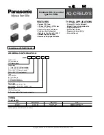
P o D IDENTIFYING
2
DOT
POSITION
RATED D - C
L E AD
0
VOLT AGE
4 6
1 2 5
250
RESISTOR
R E SI STANCE
0
300
2700
6500
NOTE
RELAYS ARE S H I P P E D O N T H E
125
VOLT TAP
L E A D
@
184A316
Fig. 23. Sele ction o f Proper Voltage Tap for A u xi li ary
Switch ( CS- 1) Operation.
screwed in completely and the other plug run in or
out until the proper operating time has been obtained.
Recheck the permanent magnet adjustment. If the
operating time for this c alibration point has changed,
readjust the permanent m agnet and then recheck the
electromagnet plug adjustment.
Contactor Switches
and
Adjust the contact gap for approximately .04
7".
A) Close the contacts of the C O and pass suf-
B) Close contacts of instantaneous overcurrent
unit
(I)
and directional unit (D). Pass sufficient d. c.
current through the trip circuit to close contacts of the
(ICS/1). This value of current should hot be greater
than the particular (ICS/1) tap setting being used.
The operation indicator target should drop freely
bringing the letter "I " into view.
A u x i l i ary Switch
Adjust the stationary core of the switch for a
clearance between the stationary core and the moving
core when the switch is picked up . This can be done
by turning the relay upside-down. Then screw up the
core screw until the moving core starts rotating. Now
back off the core screw until the moving core stops
rotating.
This indicates the points where the play
in the assembly is taken up, and where the moving
core just separates from the stationary core screw.
Back off the core screw approximately one turn and
lock in place. This prevents the moving core from
striking and sticking to the stationary core because
of residual magnetism. Adjust the contact clearance
for 3/64 " by means of the two small nuts on either
side of the Micarta disc.
Connect lead (A) to proper terminal per Fig.
23 .
Block directional unit (D) contacts
clo se and ener
gize trip circuit with rated voltage .
Contacts of
auxiliary switch (CS- 1 ) should make as indicated by
a neon lamp in the contact circuit.
R EN E WA L PA R T S
ficient d. c. current through the trip circuit to close
Repair work can be done most satisfactorily at
the contacts of the (ICS/T). This value of current
the factory. However, interchangeable parts can be
should not be greater than the particular (ICS/T) tap
furnished to the customers who are e quipped for doing
setting being used. The operation indicator target
repair work .
When ordering parts, always give the
should drop freely bringing the letter "T" into view.
complete nameplate data.
TAB L E I
D I R ECT IO�AL UNIT SENSITIVITY
AM P E R E RATI NG
R E LAY TY P E
O F
VAL U ES F O R MI N. P I CKUP
t
PHASE ANG L E R E LAT I ONSH I P
TIM E-O V E RCU R R E N T
U N I T
VOLTS
AMP E R E S
. 5-2. 5
1
2
. 0
IRP
2-6
1
4 . 0
IRD (Voltage
Unit)
1
4 . 0
4- 1 2
1
8 . 0
0 . 5
. 5- 2. 5
IRC
2-
6
. 5 7
IRD (Current
6
Unit)
4- 1 2
1 . 0
t
The energization
quantities
are
input quantities
at
the relay
terminals.
t t Maximum torque angle.
I lagging V by 60°
T
t
I in-pha� with V
I
lagging V by 60°
t t
I in-phase with V
I 0 leading Ip
In-phase
I0 leading IP
by 40° t t
by 40° t t
6,
When normal system conditions
limit the current to less than twice pickup . performance may b e improved b y sel
lecting a higher current C. T.
tap to energize the polarizing circuit.
27
www
. ElectricalPartManuals
. com