Troubleshooting and Maintenance
6-4
6
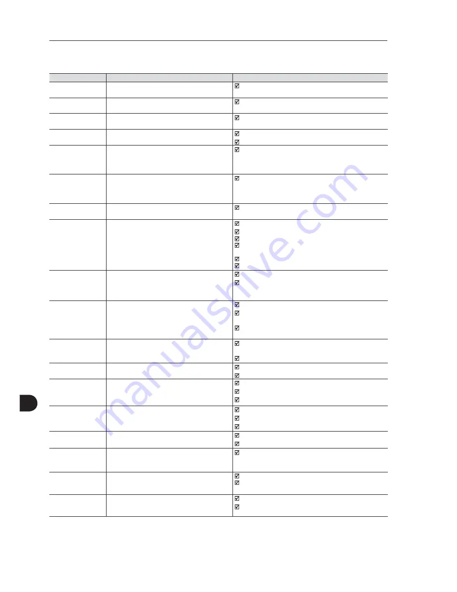
Fault/Alarm
Description
Possible Causes
F080:
CPU Watchdog
Microcontroller watchdog fault.
Electrical noise.
F082:
Copy Function Fault
Fault while copying parameters.
An attempt to copy the keypad parameters to an inverter with
a different firmware version.
F084:
Auto-diagnosis Fault
Auto-diagnosis fault.
Defect in the inverter internal circuitry.
A088:
Keypad Comm. Fault
Indicates a problem between the keypad and con-
trol board communication.
Loose keypad cable connection.
Electrical noise in the installation.
A090:
External Alarm
External alarm via digital input.
Note:
It is required to set a digital input to "No external
alarm".
Wiring was not connected to the digital input (DI1 to DI8) set
to “No external alarm”.
F091:
External Fault
External fault via digital input.
Note:
It is required to set a digital input to "No external
fault".
Wiring was not connected to the digital input (DI1 to DI8) set
to “No external fault”.
F099:
Invalid Current Offset
Current measurement circuit is measuring a wrong
value for null current.
Defect in the inverter internal circuitry.
A110:
High Motor
Temperature
Alarm related to the PTC temperature sensor instal-
led in the motor.
Note:
- It may be disabled by setting P0351=0 or 2.
- It is required to set the analog input / output to the
PTC function.
Excessive load at the motor shaft.
Excessive duty cycle (too many starts / stops per minute).
Surrounding air temperature too high.
Loose connection or short-circuit (resistance < 100
:
) in the
wiring connected to the motor termistor.
Motor termistor is not installed.
Blocked motor shaft.
A128:
Timeout for Serial
Communication
Indicates that the inverter stopped receiving valid
messages within a certain time interval.
Note:
It may be disabled by setting P0314=0.0 s.
Check the wiring and grounding installation.
Make sure the inverter has sent a new message within the
time interval set at P0314.
A129:
Anybus is Offline
Alarm that indicates interruption of the Anybus-CC
communication.
PLC entered into the idle state.
Programming error. Master and slave set with a different
number of I/O words.
Communication with master has been lost (broken cable,
unplugged connector, etc.).
A130:
Anybus Access Error
Alarm that indicates an access error to the
Anybus-CC communication module.
Defective, unrecognized, or improperly installed Anybus-CC
module.
Conflict with a WEG option board.
A133:
CAN Not Powered
Alarm indicating that the power supply was not
connected to the CAN controller.
Broken or loose cable.
Power supply is off.
A134:
Bus Off
Inverter CAN interface has entered into the bus-off
state.
Incorrect communication baud-rate.
Two nodes configured with the same address in the network.
Wrong cable connection (inverted signals).
A135:
CANopen
Communication Error
Alarm that indicates a communication error.
Communication problems.
Wrong master configuration/settings.
Incorrect configuration of the communication objects.
A136:
Idle Master
Network master has entered into the idle state.
PLC in IDLE mode.
Bit of the PLC command register set to zero (0).
A137:
DNet Connection
Timeout
I/O connection timeout - DeviceNet communication
alarm.
One or more allocated I/O connections have entered into
the timeout state.
F150:
Motor Overspeed
Overspeed fault.
It is activated when the real speed exceeds the value
of P0134+P0132 for more than 20 ms.
Wrong settings of P0161 and/or P0162.
Problem with the hoist-type load.
F151:
FLASH Memory
Module Fault
FLASH Memory Module fault (MMF-01).
Defective FLASH memory module.
Check the connection of the FLASH memory module.
7DEOHFRQW´)DXOWVµ´$ODUPVµDQG3RVVLEOH&DXVHV
Содержание 105 A
Страница 3: ...2 Revision Description Chapter 1 First Edition 2 General Revision Summary of Revisions...
Страница 17: ...General Instructions 2 10 2...
Страница 49: ...Installation and Connection 3 32 3...
Страница 63: ...First Time Power Up and Start Up 5 10 5...
Страница 79: ...Option Kits and Accessories 7 6 7...
Страница 88: ...Technical Specifications 8 9 8 Frame B Figure 8 3 Inverter dimensions frame B Dimensions in mm in...
Страница 89: ...Technical Specifications 8 10 8 Frame C Figure 8 4 Inverter dimensions frame C Dimensions in mm in...
Страница 90: ...Technical Specifications 8 11 8 Frame D Figure 8 5 Inverter dimensions frame D Dimensions in mm in...


