14
ASSEMBLY & ADJUSTMENTS
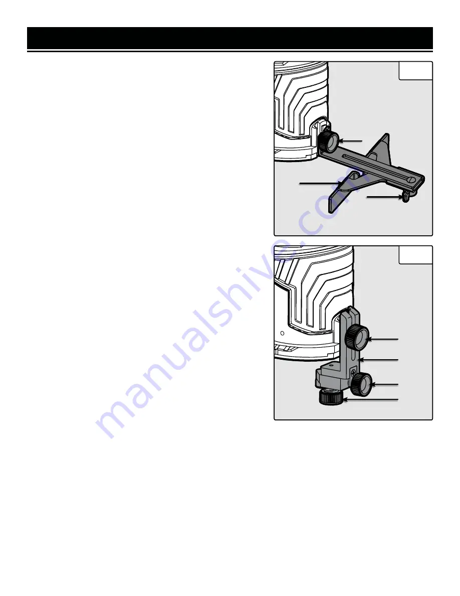
CUTTING ALONG A STRAIGHT EDGE
What you’ll need:
• Straight Fence Guide
• Workpiece with a Straight Edge
The straight guide fence is used to create straight cuts along a
workpiece with a straight edge that can be followed. To attach the
straight cut fence:
1. Attach the straight fence guide (Fig. 7 - 1) to the straight base
by loosening the guide knob on the straight base (Fig. 7 - 2). Align
the straight fence guide with the straight base and tighten the guide
knob.
2. Adjust the offset distance of the straight fence by loosing the
straight fence knob (Fig. 7 - 3) and adjusting the position of the
fence. Tighten the straight fence knob at the desired position. Make
sure all adjustment knobs are securely tightened before operating
the trim router.
3. Slide the fence along the straight reference edge of your work-
piece, moving the router along the edge in a straight line.
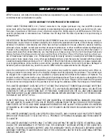
CUTTING ALONG A PROFILE
What you’ll need:
• Trim Guide
The trim guide helps maintain an equal cutting distance along the
edge of an irregularly shaped workpiece.
1. Mount the trim guide (Fig. 8 - 1) to the straight base by loosening
the guide knob (Fig. 8 - 2) on the base and sliding the trim guide
into the alignment slots at the rear of the straight base. Tighten the
guide knob to secure the trim guide.
2. The trim guide can be adjusted to different vertical depths de-
pending on router bit length and workpiece thickness. Loosen the
guide knob (Fig. 8 - 2) on the base and slide the trim guide to the
desired height. Make sure to securely tighten the guide knob before
using the trim router.
3. The trim guide bearing can be adjusted to different lateral depths
depending on the diameter of the router bit and the desired lateral
depth of cut. To adjust the lateral depth of the trim guide, first loos-
en the locking knob (Fig. 8 - 3) on the bottom of the trim guide. To
set the lateral depth, rotate the lateral adjustment knob (Fig. 8 - 4)
to the desired position. Turn the knob clockwise to increase the lat-
eral cutting depth and counterclockwise decrease the cutting depth.
4. Make sure that all adjustment knobs are securely tightened be-
fore operating the trim router.
1
3
2
Fig. 8
1
4
3
2
Fig. 7
Содержание RT1460
Страница 19: ...19 EXPLODED VIEW PARTS LIST ...
Страница 22: ...22 NOTES ...
Страница 23: ...23 NOTES ...
Страница 24: ...V 2022 05 24 THANKS FOR REMEMBERING ...


