WELDMAN
SEMI-AUTOMATIC LCD POWER MIG 210 MIG / MAG / MMA / TIG DC LIFT
Page 5
V.
INSTALLATION
Welder set on a flat and dry surface with a capacity suitable for the weight in order to avoid its overturning.
The device should be placed in a well ventilated area with free air circulation, away from flammable objects.
Make sure not enter the welder dust, corrosive vapors and moisture.
The unit should be set in such a place, not to get into it from welding spatter.
CONNECTING TO NETWORK
Before the electrical connection:
- check whether the data on the plate correspond to the values of the welding voltage and frequency of the network devices in the workplace
- check that the mains supply for the required input power
- check whether the fuse values are consistent with those given in the technical data
- Check the wiring grounding welding.
Welding wire is supplied with a 230V plug.
ELECTRICAL CONNECTION SHOULD BE CARRIED OUT BY QUALIFIED PERSONNEL OR EXPERIENCED
PREPARATION TO WORK:
1) welding machine before connecting to the network, make sure that the main switch on the rear
1) welding machine before connecting to the network, make sure that the main switch on the rear
the panel is in the OFF position
2)
Flux for welding (
without cover gas) operating handle 15 MB AK fastened to the socket euros
2)
Flux for welding (
without cover gas) operating handle 15 MB AK fastened to the socket euros
2)
Flux for welding (
without cover gas) operating handle 15 MB AK fastened to the socket euros
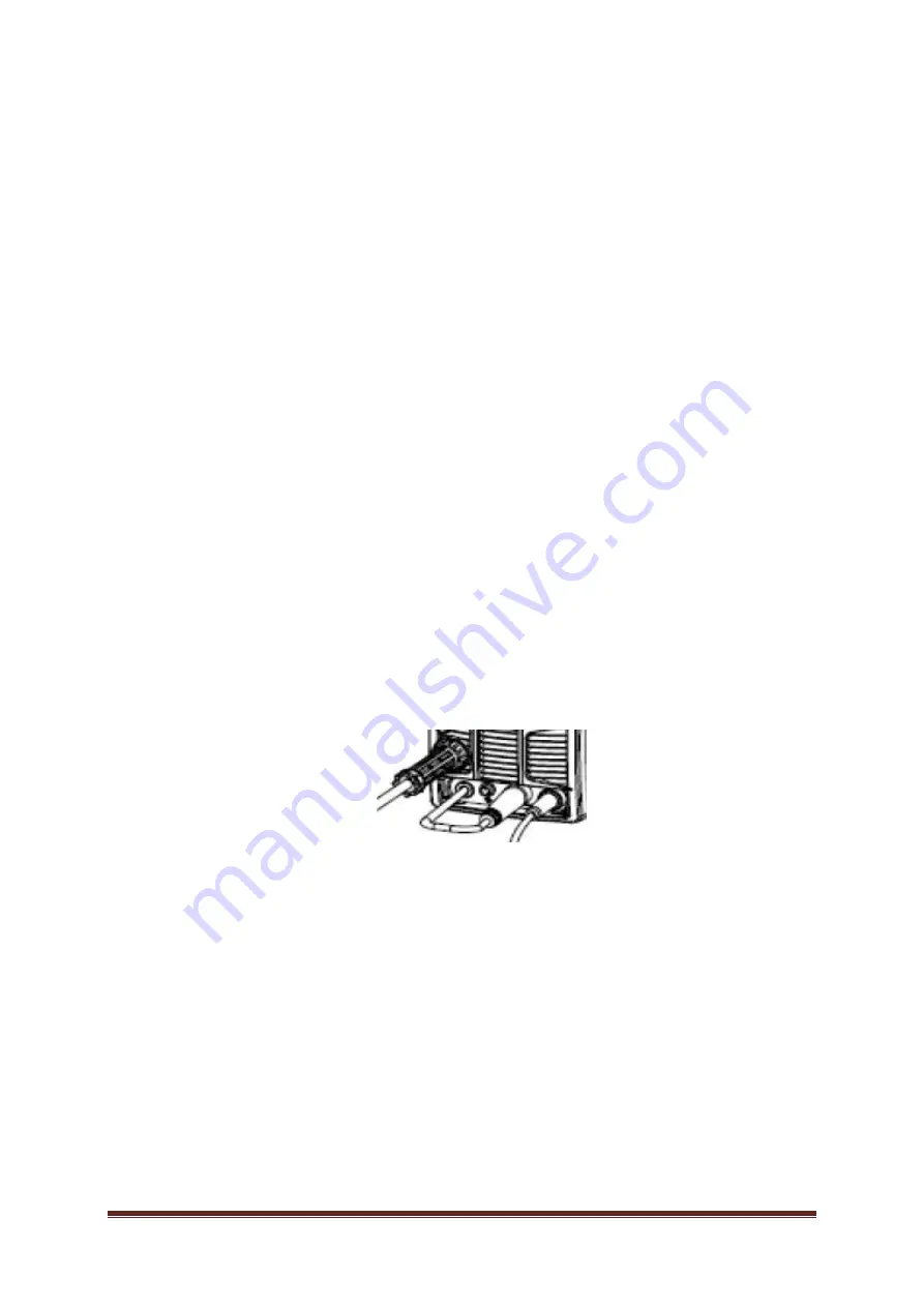
(3) the reversal of the wire holder into the socket of the negative polarity (-), hollow clamp on the welded material and the plug ground
cable to the socket on the positive polarity (+)
3)
MIG / MAG (
gas shield), an operating handle MB AK 15 are fastened to the EURO (3)
3)
MIG / MAG (
gas shield), an operating handle MB AK 15 are fastened to the EURO (3)
3)
MIG / MAG (
gas shield), an operating handle MB AK 15 are fastened to the EURO (3)
the reversal of the wire holder bay of positive polarity (+), hollow clamp on the welded material and the plug ground cable to the
socket on the negative polarity (-)
4) TIG LIFT
WP plug of the control valve 26 to fix a socket
4) TIG LIFT
WP plug of the control valve 26 to fix a socket
4) TIG LIFT
WP plug of the control valve 26 to fix a socket
negative polarity (-), hollow clamp on the welded material and the plug ground cable to the socket on the positive polarity (+)
5) welding MMA
hollow clamp are fastened at the welded material while the
5) welding MMA
hollow clamp are fastened at the welded material while the
5) welding MMA
hollow clamp are fastened at the welded material while the
connecting cables to the follow the instructions of the manufacturer of the electrodes: the most common plug wire from the electrode
holder fastened to the outlet of the positive polarity (+) and connect the ground cable to the socket of the negative polarity (-)
6) be prepared protective clothing (apron, boots and hood / welding helmet)
6) be prepared protective clothing (apron, boots and hood / welding helmet)
The above steps should be performed only when the welding device is disconnected from the power supply.
GAS CONNECTION TO WORK gas shielded MIG / MAG:
•
gas cylinder secured against tipping
•
Remove protection and for a moment to open the gas valve to remove debris
•
gas regulator mounted on the bottle
•
connect wire welder (rear exit gas) with a cylinder
•
unscrew the gas valve before starting the welding and spin at the end of


