background image

37

5

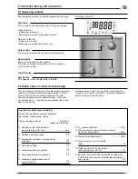
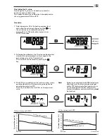
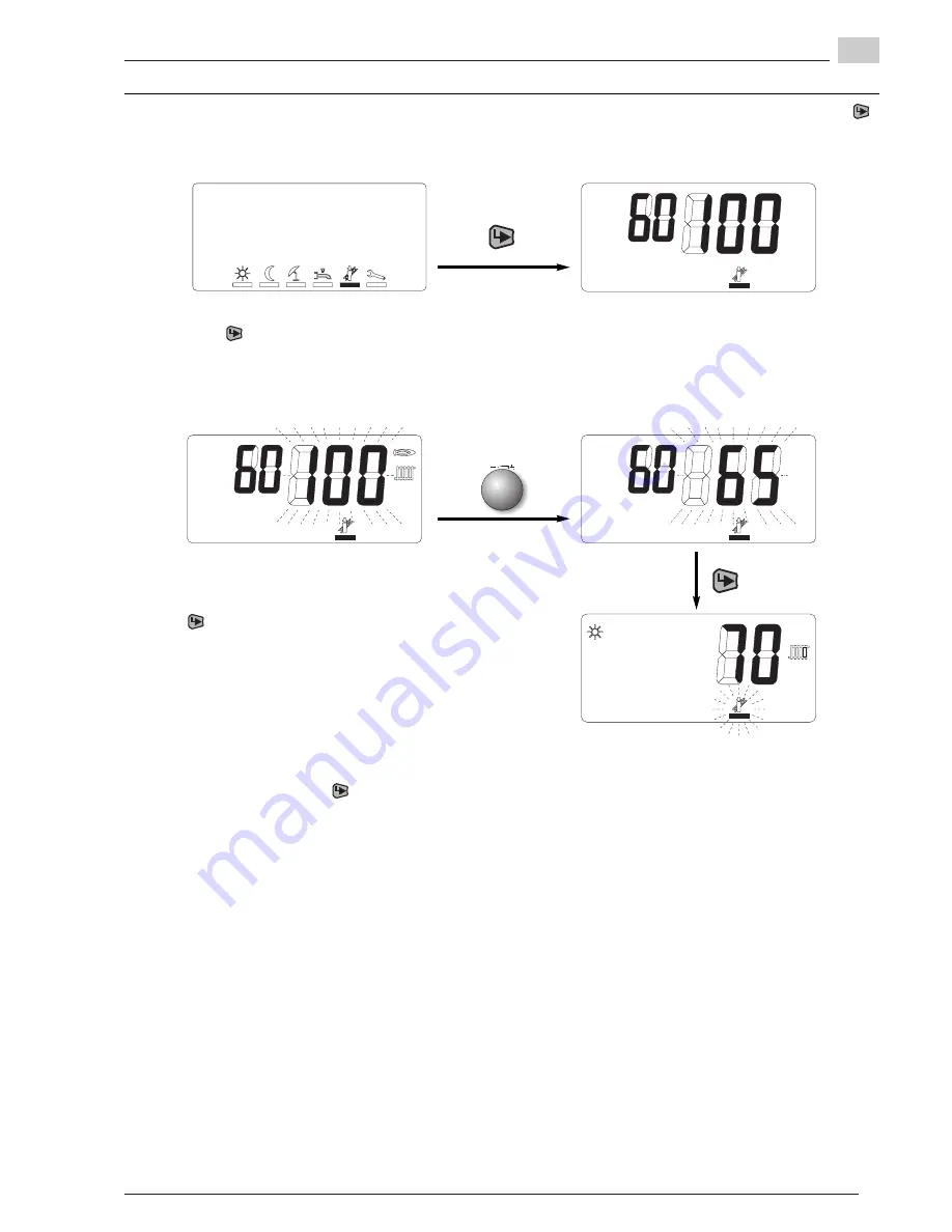
Turn the dial knob anticlockwise until the desired ratings
setting is reached. The value shown is that of the current
burner rating (in % of the maximum burner rating).

By pressing the          key again the setting level, in which
the variable heat rating can be changed from maximum 
heat rating to minimum  heat rating, is activated.

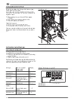
Change over to chimney sweep mode by pressing the  
key. The 3 large numbers show the current rating and the
2 smaller number show the current boiler temperature. 

5.5.2 Variable ratings setting

Move the selection cursor below the “Chimney sweep” 
symbol by turning the dial knob.

Press the        key to exit the setting level. The WTC 
remains in operation for 2 minutes with the rating last set.
Within these 2 minutes the time sequence can be
restarted in the heating engineer menu using the dial knob.
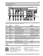
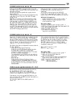
This offers the possibility to call up information in the  Info
level (see Ch. 6.3.2).

Note:

To exit the chimney sweep function, select ESC using
the dial knob and confirm with        key.

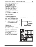
If the heat rating is reduced in the heating engineer 
level (parameter P37), the percentage ratings setting 
range is also modified, that means, as the min. rating
of the boiler is predetermined, the percentage value 
displayed increases accordingly. 

Содержание thermo condens WTC 15-A

Страница 1: ...Condensing boilers Weishaupt Thermo Condens WTC 15 A WTC 25 A and WTC 32 A 83247602 1 2008 Installation and operating instructions manual ...

Страница 2: ...D 92 42 EC Efficiency Directive EMC 2004 108 EC Electromagnetic Compatibility Directive these products are labelled as follows 0063 BM 3092 The product complies with the prototype tested by the Notified Body 0063 Schwendi 07 01 2008 ppa ppa Dr Lück Denkinger Manufacturer certification to 1 BImSchV This is a declaration that the condensing wall hung gas boiler WTC 15 25 32 complies with the require...

Страница 3: ... 4 Mains water connection 21 4 5 Filling with water 21 4 6 Electrical connection 22 4 6 1 External connections WCM 23 4 6 2 Converting unit version H 0 to version H 24 4 6 3 Connecting a 3 way change over valve 25 4 6 4 Connecting an external pump 25 4 6 5 Remote load control 26 4 6 6 Connecting temperature sensors for calorifier control variation P1 and P2 26 4 7 Gas side connection 28 4 8 Conden...

Страница 4: ...ely selectable input and outputs 53 7 6 5 Regulation with one calorifier sensor 54 7 6 6 Regulation with two calorifier sensors 54 7 6 7 Regulation with hydraulic de couple 56 8 Safety and monitoring function 58 8 1 Temperature monitoring 58 8 2 Sensor monitoring 58 8 3 Heating frost protection function 59 8 4 DHW frost protection version W 59 9 Cause and rectification of faults 60 10 Service 65 1...

Страница 5: ...sing the operating instructions to the plant operator prior to hand over He should also inform the plant operator that these instructions should be kept with the heating appliance The address and telephone number of the nearest service centre should be entered on the reverse of the operating instructions The plant operator must note that an agent of the contractor or other suitably qualified perso...

Страница 6: ...n Safety measures in normal operation Only use the equipment when all safety devices are fully functional At least once a year the equipment including the safety devices should be checked for signs of visible damage and to ensure that the safety devices are operating correctly More frequent safety checks may be required depending on plant conditions Electrical safety Before starting work isolate p...

Страница 7: ...n joints with foam forming or similar media which do not cause corrosion Max Weishaupt GmbH D 88475 Schwendi Nominal heat loading heating reduced to max __________kW General information for gas operation When installing a gas combustion system regulations and guidelines must be observed i e Local Codes of Practice and Regulations The subcontractor responsible for the installation or changes to the...

Страница 8: ...ough a flue gas duct made from Polypropylene PP to the unit exit from where a number of different ducting systems from the Weishaupt flue gas air system WAL PP are available Observe installation and operating instructions WAL PP Safety equipment An internal flue gas temperature limiter max 120 C and a safety temperature limiter switch off the unit at excess temperature 3 2 2 Important components H...

Страница 9: ...he modulation range can be adjusted in the heating engineer level using parameter P42 and P43 This pump matches the unit throughput to the rating and reduces electrical consumption The resulting supply pressure within the modulating range can be determined using the diagram on the right For a detailed description of the controller function see Ch 7 6 Note Following change over into DHW operation v...

Страница 10: ...sure mbar Throughput l h Speed 100 80 60 40 20 Speed 100 80 60 40 20 Version with PWM pump On condensing boilers with PWM Pulse width modulation modulating heating circuit pump the maximum modulation range of the pump in its factory presetting is 30 60 WTC 15 A 30 70 WTC 25 A and 30 80 WTC 32 A The modulation range can be adjusted in the heating engineer level using parameter P42 and P43 This pump...

Страница 11: ...ghput l h Stage 3 Stage 2 Stage 1 Diagram pressure loss WTC 15 A 25 A 32 A version H 0 without pump 700 600 500 400 300 200 100 600 0 1200 0 800 400 200 2000 1800 1600 1400 1000 2200 800 Pressure loss mbar Throughput l h Pressure loss unit H 0 The diagram on the right shows the pressure loss of the WTC unit without integrated pump to be able to carry out the hydraulic design of the installation Si...

Страница 12: ...Ragulating range Expansion vessel The table enables an evaluation to establish if the expansion vessel fitted content 10 l is sufficient or if an additional expansion vessel is required The following key data was taken into account for the table Flow pressure of the expansion vessel is equal to the static installation height above the heat exchanger e g height 10 m flow pressure 1 0 bar Maximum op...

Страница 13: ... only but without pump and expansion vessel Version W Unit with integrated 3 way valve for DHW preparation in combination with Weishaupt water heaters Version C Unit with integrated DHW preparation via plate heat exchanger and throughput sensor for acquisition of water quantity drawn 3 3 2 Version H 3 4 5 6 7 8 9 10 11 12 13 14 15 16 17 18 19 21 22 15 23 24 18 25 26 27 28 29 1 2 20 3 3 Basic const...

Страница 14: ... version W is equipped with connection pipes for connecting a water heater Note The expansion tank is integrated in WTC 15 A WTC 25 A as well as WTC 32 A vers W 1 3 4 2 1 Heating flow 2 Heating return 3 Flow to water heater 4 Return from water heater 3 3 3 Version H 0 Version H 0 is a unit for heating operation without DHW preparation The heating pump and the expansion vessel are usually fitted on...

Страница 15: ... temperature so that warm water is available immediately the tap is opened This function can be switched off Version C is equipped with a booster function to ensure total DHW comfort which increases the burner rating to approx 28 kW with a drawn quantity of over 4l min and an outlet temperature 50 C This function can be switched off in the heating engineer level parameter P62 The plate heat exchan...

Страница 16: ... Due to the water vapour content in flue gases with low temperature and the additional condensation created in the chimney condensing boilers can only be connected to moisture resistant house chimneys The flue gas ducts must comply with local authority regulations and country specific requirements DE DVGW TRGI AT ÖVGW CH SVGW VKF Guidelines Number 3 4 8 Issue 1993 Building regulation approved flue...

Страница 17: ...p water quantity Determine if measures for water treatment are necessary using the diagram If the fill and top up water lies in the range of the upper limit curve Treat fill and top up water If the fill and top up water lies in the range of the lower limit curve the water does not need to be treated Note Document fill and top up water quantity 0 200 400 600 800 1000 1200 1400 1800 1600 0 5 10 15 2...

Страница 18: ...ineralised water following commissioning after approx 4 weeks of operation during the annual service If necessary adjust pH value of heating water by adding Trisodium Phosphate Softening cation exchanger Damage to the unit due to raised pH value Corrosion could damage the system Following softening by cation exchanger the pH value must be stabilised due to the self alkalisation of the heating wate...

Страница 19: ...F as well as local and cantonal regulations must be observed Furthermore the EKAS guideline Guideline for Liquid Petroleum Gas part 2 must be observed DANGER 4 1 Safety notes on installation 4 2 Delivery transport storage Packaged in shipment box The WTC is delivered complete with accessories packaged in one strong shipment box The shipment packaging is best removed with the unit upright Only tran...

Страница 20: ...it open clamp fastener and remove cover upwards DANGER Fit wall bracket 40 50 790 127 25 61 5 227 46 5 1 260 Fit wall bracket Fit wall bracket 1 enclosed to the wall with the fixing screws supplied The suitability of the wall plugs enclosed should be checked depending on the construction of the wall A gradient of 3 towards the unit should be provided for the flue gas ducting at 1metre this is equa...

Страница 21: ...d Unsuitable water results in scaling and corrosion formation and can cause damage to the condensing boiler Centre position three way valve Check pre pressure of the diaphragm expansion vessel Prior to first commissioning the heating system should be flushed with at least twice the amount of the system content to remove contaminants Swarf rust scale sludge etc can influence the operational safety ...

Страница 22: ... 230V 50 Hz The gas condensing boiler WTC is wired ready for connection The cover of the electrical installation duct must be removed for the electrical installation Insert the cable from the rear through the recess into the unit The electrical connection must be carried out by a qualified electrician Changes to the internal boiler wiring are not permitted Shell clamps should be used if flexible c...

Страница 23: ...ee relay output 230VAC 8A DC 60V 5A function dep on configuration eBUS 7 blue Connection of add control components WCM FB EM KA B11 8 white De couple sensor variation P2 P3 Ch 7 6 6 7 6 7 0 99 C B1 9 green External sensor type QAC 31 Order No 660 186 40 50 C NTC 600 Ohm N1 4 20 mA remote load control Ch 4 6 5 4 20 mA B3 10 yellow Tank sensor NTC 12kOhm 0 99 C Optional B10 DHW calorifier control se...

Страница 24: ...5 A 25 A 3 stage pump PWM pump WTC 32 A PWM pump The pump is supplied ready to plug in and should be connected to plug slot 17 1 2 3 4 5 6 7 8 9 10 Connect internal boiler pump St 17 St 18 St 20 St 19 Internal boiler plug rail Control line only with PWM pump 230V H1 F1 230V 4AT 230V H2 MFA VA eBUS B11 B1 N1B3 eBus PC F2 24V 4AT 1 0 Reset key Enter key Dial knob ...

Страница 25: ...ue 4 Control via MFA P13 4 Control via VA P14 4 3 way change over valve Order No 409 000 05 73 2 Servomotor with connection cable Order No 409 000 05 71 2 Connect 3 way change over valve 4 6 4 Connecting an external boiler pump brown Control via MFA WCM CPU Control via VA WCM CPU black blue brown black blue The external boiler pump can be controlled via output MFA or VA To achieve the required fun...

Страница 26: ...h diaphragm grommet in installation area Scope of delivery calorifier sensor connection Connecting calorifier sensor B10 Order No 481 000 00 16 2 4 6 5 Remote load control The control cable 4 20 mA is connected to input B1 N1 plug 9 independent of polarity The WCM automatically recognises the signal and displays configuration _t _ when it is switched on The available signal is interpreted as suppl...

Страница 27: ...rommet 5 Connect wire ends to plug part B10 and secure with tension relief cable ties 6 Connect calorifier sensor to socket B10 and plug in 7 When retrofitting to an existing installation the unit has to be reconfigured via parameter P10 Ch 6 3 3 Connecting calorifier cable loom ST20 Note Detailed description for the control of calorifier tanks see Ch 7 6 5 and Ch 7 6 6 ...

Страница 28: ...supply line recommissioning may only be carried out once the appropriate components have been vented by the gas board or their appointed sub contractor Unit connection Use the elbow or straight gas connection cock available as an accessory to connect the unit to the gas supply The gas board will also inform you if you require an approved gas filter or thermal shut off valve required to comply with...

Страница 29: ...ays be filled with water If the siphon is empty flue gas can escape Fill siphon with water top up if flue gas can be smelled Note When installing the siphon ensure that the condensate is expelled completely as a blockage in the condensate line will cause operational problems Therefore do not connect the condensate hose permanently to the waste pipe but mount it free flowing e g into an outlet hopp...

Страница 30: ... independent operation by non closing supply air ducts Only CE certificated or locally tested and approved flue gas systems must be used The Weishaupt Flue gas air system WAL PP see installation and operating manual WAL PP offers approved kits and individual components The flue gas duct must be gas tight Carry out soundness test Note If a plastic flue gas system is connected which is approved for ...

Страница 31: ...d if any item can be adjusted it should also be checked that it has been set correctly Furthermore the correct fusing of the circuits and the measures for contact protection of electrical equipment and of wiring must be checked Checklist for initial commissioning Please tick the work carried out and enter the relevant measurement values Commissioning protocol Remarks Measurement value Heating syst...

Страница 32: ...vice The result of the soundness test must be certified on the engineers report Open closing screw on test point Pe by approx 1 rotation Connect pressure measuring device to Pe Connect aspirator with T piece Create test pressure The test pressure should be 100 mbar Pressure loss within 5 minutes max 1 mbar Only non corrosive solutions must be used to locate leaks The gas ball valve should be inclu...

Страница 33: ...onfiguration detected in flashing codes If a calorifier or de couple sensor has been detected by the WCM CPU the relevant control variation will be displayed after approx 7 seconds instead of the boiler type The configuration detected is displayed flashing for approx 20 seconds By pressing the button during this time the configuration is saved If the button is not pressed an automatic backup is ca...

Страница 34: ...should be carried out measuring the O2 content at nominal load and partial load conversion table O2 CO2 see appendix Open gas ball valve The electrical wiring must have been tested Water pressure is available cocks are open sufficient heat demand is ensured The WTC has been factory preset Due to its fully automatic compound regulation an adaptation to various gases from one gas family is not requi...

Страница 35: ...ue can be saved by pressing the key 3 The WTC now modulates to the minimum rating where possible deviations in the lower ratings range can be equalised by adjusting P72 The entry is carried out as for P39 as O2 adjustment value Note Following an adjustment with P39 adjustment effective across the total modulating range and or P72 adjustment effective across mini mum load range of 33 50 rating the ...

Страница 36: ... gas system For room air independent operation a soundness test of the flue gas system via an O2 measurement within the internal space of the condensing boiler is required Fit hose 4 through the test point in the supply air aperture 2 into the condensing boiler Seal test point in the supply air aperture 2 Connect test sensor 5 to the hose 4 Close cover of condensing boiler Start condensing boiler ...

Страница 37: ... Move the selection cursor below the Chimney sweep symbol by turning the dial knob Press the key to exit the setting level The WTC remains in operation for 2 minutes with the rating last set Within these 2 minutes the time sequence can be restarted in the heating engineer menu using the dial knob This offers the possibility to call up information in the Info level see Ch 6 3 2 Note To exit the chi...

Страница 38: ...91 997 1003 1009 1015 1021 1027 1033 1036 0 0 9378 0 9437 0 9497 0 9546 0 9605 0 9664 0 9724 0 9783 0 9842 0 9901 0 9961 1 0020 1 0079 1 0138 1 0197 1 0227 2 0 9310 0 9369 0 9427 0 9476 0 9535 0 9594 0 9653 0 9712 0 9770 0 9829 0 9888 0 9947 1 0006 1 0064 1 0123 1 0153 4 0 9243 0 9301 0 9359 0 9408 0 9466 0 9525 0 9583 0 9642 0 9700 0 9758 0 9817 0 9875 0 9933 0 9992 1 0050 1 0079 6 0 9176 0 9234 ...

Страница 39: ...play for a warning or lockout with relevant identification code or current burner rating in chimney sweep function 6 2 End user level 1 2 3 4 5 6 7 8 9 0 6 1 Operating levels The operation is divided into two operating levels Level 1 is the end user level and can be accessed directly If an FS remote control station is fitted only the chimney sweep function can be called up in level 1 Level 2 The h...

Страница 40: ...e settings are carried out on the controllers If communication fails the symbols for emergency operation are faded in Display Enter Range Factory Note pre setting No external sensor Normal temperature setpoint Setback temperature connected to B1 Standby operation 60 C Limit value adjustable Max flow temperature by Parameter P30 P31 heating engineer level Room temperature setpoint 15 C 35 C 22 C Ex...

Страница 41: ...l is exited Press enter key 6 3 Heating engineer level Note Exiting the heating engineer level Turn dial knob until ESC is displayed then press enter key The heating engineer level symbol line is displayed i Info mode P Parameter mode Error memory By turning the dial knob the selection cursor can be placed under a symbol The selection is activated by pressing the enter key ...

Страница 42: ...C I39 Temperature calorifier B11 P2 P3 C System info I40 Daily switch cycle counter burner 0 999 I41 Daily operating hours counter burner 0 255 h I42 Switch cycle counter burner x 1000 I43 Operating hours counter burner h x 100 I44 Software version v Version r Revision v r I45 Time since last service h x 10 E ES SC C exit menu 6 3 2 Info mode Here specific system values can be displayed By turning...

Страница 43: ...setting parameters can be found in the following table The table also shows the factory settings in column WTC 15 25 43 6 Display Phase description 1 1 Standby control fan 2 2 Prepurge speed achieved Tv 0 3 Countdown of prepurge in secs 4 4 Ignition speed achieved 0 Tz 5 Flame formation time in 0 1 x secs 6 6 Burner in operation control active 7 7 Gas valve control V1 8 8 Gas valve control V2 9 9 ...

Страница 44: ...program 7 Heating circuit pump remote controlled via WCM FS with address 1 P14 0 7 1 Function variable output VA Ch 7 6 4 0 Liquid petroleum gas pre valve 1 Forward reporting of lockout 2 Feeder pump in front of hydr de couple 3 Heating circuit pump 4 DHW load pump 3 way change over valve 5 DHW circulation pump 6 Program controlled via FS Addr 1 Circulation programme 7 Heating circuit pump remote ...

Страница 45: ...tion when P40 0 for DHW operation 3 min With calorifier control no lag for DHW P42 x 20 P43 30 Minimum pump rating heating Only with PWM pump P43 x P42 100 60 3 Maximum pump rating heating P44 x 0 7 4 K Volume flow control in conjunction with Only in conjunction with hydr de couple hydr de couple and de couple control P3 Ch 7 6 7 only with PWM pump Deactivated P45 x 20 100 60 Pump rating domestic ...

Страница 46: ...Ch 5 4 1 Automatic configuration 1 On WTC 32 Factory setting 13 2 On WTC 25 Parameter value 32 100 Factory setting 32 WTC 32 Parameter value 31 100 Factory setting 31 3 On WTC 25 Factory setting 70 WTC 32 Factory setting 80 P17 P18 special level If parameter P17 has been programmed for the function Special level with the setting 2 the WTC can provide an additional temperature level If contact H2 i...

Страница 47: ...rature B1 X C 34 DHW temperature B3 X C ESC Exit menu Here the last 6 error messages can be called up in the form of an error code see Ch 9 of the WTC using the dial knob 6 3 4 Error memory Table of warning and error messages cause and rectification of lockouts see Ch 9 Exiting the level Turn the dial knob until ESC is displayed and confirm with key By pressing the enter key again the system condi...

Страница 48: ...via Weishaupt eBUS adapter W EA from eBUS via RS 232 interface to PC The W EA as well as the Service Software WCM Diagnostic are available as accessories Your PC should meet the following requirements Processor from 400 MHZ Operating system WINDOWS 95 or higher RAM 64 MB Resolution screen grafics card 800 x 600 Pixel The software makes the following functions available Display of operating conditi...

Страница 49: ...l symbol Ch 6 2 2 Domestic hot water program for setback normal operation P17 1 7 1 Constant flow temperature control The WCM not only carries out the regulating and control functions for the boiler but also the control of the heating systems and domestic hot water operation The heating controller contains basic functions which have an effect in all the following variations The boiler flow tempera...

Страница 50: ...er level P22 see diagram heating reference line The room temperature setpoint adjustable in the end user level is also considered see diagram influence room temperature setpoint If using an inbuilt digital clock WCM DU different room temperature setpoints are possible for day night When fitting a WCM remote control FB accessory the setting of the room temperature setpoints is carried out by remote...

Страница 51: ... A heat up procedure is initiated in setback operation if the DHW minus the subtraction value is not maintained This requires either the digital clock WCM DU connection of second channel to plug 4 H2 or the remote control WCM FB both available as accessories Setting both temperatures Normal temperature in end user level symbol Setback temperature in heating engineer level normal temperature P53 Pa...

Страница 52: ...nute in heating operation the pump is operated at the rating defined in P43 Once modulation has been released the control is carried out within the programmed load limits P42 P43 Parametere settings P42 minimum pump rating C P43 maximum pump rating B P45 pump rating DHW operation A 7 6 Special functions 7 6 1 PWM pump 7 6 2 Pump control logic in heating operation The following pump control logic i...

Страница 53: ...g F24 is displayed If the contact opens the warning automatically terminates Liquid Petroleum gas pre valve P13 P14 0 As soon as the burner starts due to a heat demand the contact is closed This allows the control of an additional liquid petroleum gas valve This option cannot be used on installations with gas pressure switch Lockout and warning transmission P13 P14 1 The contact is open if the ins...

Страница 54: ...P13 P15 4 the pump does not run on after DHW operation is completed For this type of regulation a calorifer sensor NTC 5kΩ Order No 660 228 has to be connected to sensor input B10 Ch 4 6 6 Input B11 is not connected This type of operation makes sense if only the top part of the calorifer is to be loaded by the WTC The loading of the lower part of the calorifier area is carried out via external hea...

Страница 55: ...automatically terminates Liquid Petroleum gas pre valve P13 P14 0 As soon as the burner starts due to a heat demand the contact is closed This allows the control of an additional liquid petroleum gas valve This option cannot be used on installations with gas pressure switch Lockout and warning transmission P13 P14 1 The contact is open if the installations is operating without fault As soon the WC...

Страница 56: ...DHW operation With DHW operation the modulation control is carried out via the internal flow sensor Consequently the hydraulic alignment of the DHW circuit before the de couple using a 3 way valve is also possible DHW operation is completed with a pump run on of 3 minutes 7 6 7 Regulation with hydraulic de couple P3 Sensor connection variation P3 1 230V 2 230V 3 H1 4 H2 5 MFA 6 VA 7 eBUS 8 B11 9 B...

Страница 57: ... activated At the same time warning F24 is displayed If the contact opens the warning automatically terminates Liquid Petroleum gas pre valve P13 P14 0 As soon as the burner starts due to a heat demand the contact is closed This allows the control of an additional liquid petroleum gas valve This option cannot be used on installations with gas pressure switch Lockout and warning transmission P13 P1...

Страница 58: ... Flue gas system The following functions for flue gas temperature monitoring are combined in one sensor Safety temperature limiter for flue gas Temperature measurment for display Safety temperature limiter STL flue gas If the programmed STL switch off temperature for the flue gas circuit is exceeded the fuel supply is shut off and the fan and pump run on is initiated fault display F13 To increase ...

Страница 59: ...ump continuous run on TA act Tsystem frost protction Pump continuous run off Frost protection is also effective on outputs MFA and VA with function heating circuit pump P13 P14 With calorifier regulation P1 P2 the system frost protection has no effect on the boiler circuit pump internal or connected to MFA VA TDHW 8 C Frost protection heating on TDHW 8 C switch differential DHW 2 P51 Frost protect...

Страница 60: ...lt rectification Temperatures 11 Fault Boiler temperature 105 C No water in boiler top up water Air in boiler vent boiler No boiler throughput check function of pump 12 Warning Boiler temperature 95 C No water in boiler top up water Air in boiler vent boiler No boiler throughput check function of pump 13 Fault Flue gas temperature 120 C Heat exchanger heavily soiled 14 Warning Flow temperature Air...

Страница 61: ...SCOT electrode if necessary replace With room air independent operation carry out soundness test of flue gas system Ch 5 5 23 Fault Flame simulation Check earth connections Replace WCM circuit board 24 Fault4 Underfloor heating thermostat on Check mixer input H2 is activated Check flow setpoint Check pump function 2 After 5 unsuccessful start attempts the boiler goes to lockout 3 The boiler attemp...

Страница 62: ...able parameters as per Ch 6 3 3 if necessary use WCM diagnostic Application fault BCC plug Plug in BCC Install BCC of version 3 X Invalid unit configuration Replace WCM CPU 52 Fault System fault combustion control Replace WCM CPU Invalid configuration data set Carry out initialisation of BCC Application fault BCC plug Check polling of BCC Plug in BCC and carry out initialisation 53 Fault Voltage s...

Страница 63: ...exceeds Check flue gas circulation flue gas system is factory preset limits gas tight Ch 5 5 External influences on the unit supply air due to flue gas dust or other contaminants 65 Fault New calibration value deviates too Supply air contaminated by dust and soot much from the previous value 100 calibration was not carried out following the repalcement of SCOT electrode WCM CPU or burner Ch 5 5 P3...

Страница 64: ...ble connection transmits a valid setpoint FS or EM defective 84 Warning WCM EM 4 or FS 4 no longer Check cable connection transmits a valid setpoint FS or EM defective 85 Warning WCM EM 5 or FS 5 no longer Check cable connection transmits a valid setpoint FS or EM defective 86 Warning WCM EM 6 or FS 6 no longer Check cable connection transmits a valid setpoint FS or EM defective 87 Warning WCM EM ...

Страница 65: ... test sheet 5 Complete an inspection card Variable rating setting in chimney sweep mode Ch 5 5 2 To leave chimney sweep mode turn dial knob until ESC appears then press key Service interval The operator should ensure that the combustion appliance is inspected or serviced at least once a year by an agent of the manufacturer or other suitably qualified person Set service interval The time between se...

Страница 66: ...rner and burner gasket Ch 10 3 Clean heat echanger if pressure loss is 5 0 mbar WTC 15 4 5 mbar WTC 25 or 7 5 mbar WTC 32 cleaned Service instructions cleaning kit 4 mbar Check ionissation electrode replace if SCOT base value is 70 points WTC 15 replaced 75 points WTC 25 or 78 points WTC 32 Test ignition electrode and check spark gap 3 mm 0 3 mm Clean and refill condensate water siphon check conde...

Страница 67: ...burner gasket Ch 10 3 Clean heat echanger if pressure loss is 5 0 mbar WTC 15 4 5 mbar WTC 25 or 7 5 mbar WTC 32 Service instructions cleaning kit Check ionissation electrode replace if SCOT base value is 70 points WTC 15 75 points WTC 25 or 78 points WTC 32 Test ignition electrode and check spark gap 3 mm 0 3 mm Clean and refill condensate water siphon check condensate drain Reassemble heat excha...

Страница 68: ...ling 1 Close gas isolating valve de energise unit 2 Undo electrical connections of gas valve fan and immersion coil 3 Undo 3 4 screwed union between gas valve and gas pipe 4 Remove the 4 fixing nuts on the burner cover 5 Remove burner cover with seal and flange connected gas air compound unit 6 Remove burner surface 7 Remove the 4 fixing screws on the service cover and remove service cover Dis ass...

Страница 69: ... fill siphon with water see Ch 4 8 2 Fit service cover with new seal and tighten the screws to 4 Nm torque 3 Install pre mix burner ensuring correct alignment on the adjusting struts 4 Check burner seal for damage prior to fitting the burner cover Fit burner cover to the stay bolts and tighten the nuts to 4 Nm torque 5 Connect the gas valve to the gas pipe and tighten the union nut Fit new gas sea...

Страница 70: ...himney sweep function by pressing the key The function remains active for 15 minutes The 3 digit display shows the current boiler rate The 2 digit display shows the current boiler temperature To exit the chimney sweep function turn dial knob until ESC appears then press the key After approx 90 seconds the standard display appears 90 sec ...

Страница 71: ...ural Gas LL min Standard max mbar 20 25 30 Gas flow pressure LPG B P min Standard max mbar 42 5 50 57 5 Gas flow pressure LPG B P min Standard max mbar 25 37 45 Standard efficiency at 75 60 C 107 0 96 4 Hs Standard efficiency at 40 30 C 110 0 99 1 Hs Standard emission factors Nitrous Oxide NOx mg kWh 20 Carbon Monoxide CO mg kWh 13 O2 Natural Gas2 5 5 O2 LPG1 2 5 8 Water content l 2 6 permiss max ...

Страница 72: ...ural Gas2 5 5 O2 LPG1 2 5 8 Water content l 3 5 permiss max excess operating pressure bar 3 0 Content expansion vessel l 10 Inlet pressure expansion vessel bar 0 75 Version C permissible operating pressure DHW bar 6 DHW outlet quantity l min 7 5 Burner rating in boost operation kW 28 QC to EN 483 1 Propane 2 Conversion table O2 CO2 see appendix EnEV product variables Heat rating QN at 80 60 C kW 6...

Страница 73: ...H min Standard max mbar 17 20 25 Gas flow pressure Natural Gas LL min Standard max mbar 20 25 30 Gas flow pressure LPG B P min Standard max mbar 42 5 50 57 5 Gas flow pressure LPG B P min Standard max mbar 25 37 45 Standard efficiency at 75 60 C 107 96 4 Hs Standard efficiency at 40 30 C 110 99 1 Hs Standard emission factors Nitrous Oxide NOx mg kWh 35 Carbon Monoxide CO mg kWh 17 O2 Natural Gas2 ...

Страница 74: ...4 61 55 64 58 69 Max flue gas temperature at 50 30 C C 32 46 33 47 34 53 Flue gas value group G635 G636 G62 G61 G62 G61 G62 G61 A 11 2 Electrical data Weishaupt gas condensing unit WTC 15 A WTC 25 A WTC 32 A Nominal voltage 230V 1N 50Hz 230V 1N 50Hz 230V 1N 50Hz Nominal load Version PEA pump W 101 103 121 Version PWM pump W 87 96 151 Version 3 stage pump W 97 120 Version without pump W 30 35 53 El...

Страница 75: ...ght incl cladding kg 42 49 46 520 260 260 125 ca 800 40 48 50 792 56 24 3 80 80 142 6 1 335 50 120 77 5 260 35 50 99 2 240 2 3 4 5 1 Heating flow 2 Flow water heater or domestic hot water 3 Gas 4 Return water heater or domestic water 5 Heating return 6 Condensate trap without expansion vessel ...

Страница 76: ... In heating engineer level Ch 6 3 set parameter P11 to F 7 Carry out calibration using parameter 39 see page 43 8 Burner commissioning and O2 check to Ch 5 5 9 Note setting of type of gas on name plate C Reduction of heat rating Gas rate adjustment Procedure In heating engineer level Ch 6 3 3 set parameter P37 accordingly Note reduced heat rating on name plate Gas type conversion D Wobbe table Cal...

Страница 77: ... 2185 75 740 105 292 10 27523 20 6244 50 1802 80 628 110 254 5 21078 25 5000 55 1494 85 535 0 16277 30 4029 60 1245 90 457 5 12669 35 3267 65 1042 95 393 Sensor variables DHW sensor version W NTC 12 kΩ External sensor QAC 31 NTC 600 Ω Boiler 4 core flue gas 4 core DHW sensor version C 2 core and calorifier sensor B10 B11 NTC 5 kΩ E Conversion table O2 CO2 O2 content CO2 content dry Natural Gas E N...

Страница 78: ... Burner Only on Combi units Only on units with variable pump PE Housing On off switch 0 1 230V 230V MFA H1 H2 VA B11 B1 N1 B3 F1 230V 4AT PC Reset key Enter key Dial knob eBUS Internal boiler terminal rail Terminals for external electrical equipment F2 24V 4AT 1 1 On units version H H 0 and W this terminal slot is used to plug in the accessories connection cable Order No 481 000 00 08 2 to connect...

Страница 79: ...__________ _________ __________________________________ Comments Information at the heating installation Functions commissioning faults shutdown Operation and service on the display control poss control units poss test certificate poss night setback summer operation Water pressure water top up What to do if gas can be smelled Combustion air supply Condensate outlet into domestic water system The s...

Страница 80: ... Spare parts A 1 03 1 06 1 05 1 04 1 03 1 10 1 11 1 17 1 16 1 07 1 20 1 28 1 25 1 24 1 23 1 33 1 34 1 01 1 19 1 27 1 26 1 21 1 22 1 13 1 12 1 09 1 08 1 07 1 32 1 15 1 12 1 14 1 31 1 30 1 29 1 18 1 18 1 28 1 12 1 02 1 02 1 35 ...

Страница 81: ...r el conn WTC 15 32 A 481 011 22 33 2 1 18 Screw 4 X 12 WN1411 K40 409 351 1 19 Screw DIN 7981 409 123 1 20 Cover cable duct WTC 15 25 A 481 011 02 07 2 1 21 Washer 3 5 x 10 x 0 5 Polyamid 430 020 1 22 Corner sheathing 0 8 1 0 mm 756 027 1 23 Grommet water connections Dm I 18 481 011 02 19 7 1 24 Grommet siphon Dm I 35 WTC 15 25 A 481 011 40 22 7 1 25 Grommet condensate hose Dm I 24 481 011 02 36 ...

Страница 82: ... 2 16 2 15 2 14 2 13 2 11 2 09 2 06 2 05 2 07 2 03 2 04 2 15 2 19 2 20 2 21 2 39 2 40 2 45 2 44 2 43 2 42 2 38 2 37 2 36 2 35 2 32 2 33 2 34 2 25 2 27 2 28 2 23 2 22 2 26 2 31 2 41 2 50 2 08 2 10 2 12 2 01 2 02 2 26 2 26 2 48 2 49 2 29 2 30 ...

Страница 83: ...TC 25 A 481 111 30 05 7 2 23 Service cover WTC 15 A 481 011 30 02 7 WTC 25 A 481 111 30 02 7 2 24 Double nipple R3 4 X G3 4 X 29 481 011 30 08 7 2 25 Flue gas sensor NTC WTC 15 25 A 481 011 30 26 7 2 26 Screw M 4 X 10 DIN 912 402 150 2 27 Safety plate flue gas sensor 481 011 30 27 7 2 28 Sleeve flue gas sensor WTC 15 25 A 481 011 30 28 7 2 29 Double nipple R1 4 X G3 8 Conn expansion vessel 481 011...

Страница 84: ...84 A 3 11 3 14 3 02 3 15 3 16 3 17 3 19 3 18 3 20 3 21 3 22 3 23 3 13 3 01 3 08 3 04 3 05 3 07 3 03 3 12 3 09 3 06 3 10 nur Ausführung H ...

Страница 85: ... circuit board WTC 15 32 vers H H 0 W K 481 015 22 06 2 WTC 25 vers C 481 113 22 06 2 3 12 Coded plug BCC WTC 15 A vers H H 0 W 481 011 22 11 2 WTC 25 A vers H H 0 W 481 111 22 11 2 WTC 32 A vers H H 0 W 481 301 22 11 2 3 13 Insert bridge 2 pole 716 232 3 14 Plug No 1 3 pole black Rast 5 716 220 3 15 Plug No 2 3 pole grey Rast 5 716 221 3 16 Plug No 3 2 pole turquoise Rast 5 716 222 3 17 Plug No 4...

Страница 86: ... 11 4 12 4 13 4 14 4 15 4 16 4 12 4 17 4 10 4 22 4 25 4 26 4 25 4 27 4 28 4 19 4 20 4 29 4 30 4 32 4 29 4 07 4 08 4 05 4 18 4 05 4 03 4 31 4 06 4 21 4 02 4 23 4 24 4 33 4 09 4 01 4 04 4 21 4 21 nur Ausführung H O ...

Страница 87: ...0 18 7 4 18 Connection pipe return WTC 15 25 A 481 011 40 07 2 4 19 Seal Change over valve 481 012 40 02 7 4 20 Cover plate change over valve WTC H 481 011 40 24 2 4 21 Screw M 6 X 25 DIN 912 402 371 4 22 Screw DIN 7981 St4 2x13 409 123 4 23 Mounting exp vessel top 481 011 40 03 7 4 24 Expansin vessel 481 011 40 02 7 4 25 Seal 10 X 14 8 X 2 441 077 4 26 Connection pipe WT AD WTC 15 25 A 481 011 40...

Страница 88: ...88 A 5 20 5 21 5 22 5 13 5 14 5 15 5 16 5 17 5 18 5 12 5 28 5 31 5 33 5 34 5 24 5 26 5 25 5 01 5 02 5 14 5 19 5 07 5 04 5 27 5 31 5 23 5 03 5 04 5 04 5 10 5 11 5 30 5 04 5 29 5 32 5 08 5 05 5 06 5 09 ...

Страница 89: ...ut G1 siphon 481 011 40 17 7 5 18 Condensate hose 25 X 3 X 1000 lang 481 011 40 23 7 5 19 Lid siphon WTC 15 25 A 481 011 40 18 7 5 20 Pump seal 481 011 40 05 7 5 21 Circulation pump WTC 15 A 481 011 40 13 2 PWM X WTC 15 A 481 011 40 14 2 WTC 25 A 481 011 40 03 2 PWM X WTC 25 A 481 011 40 12 2 PWM X WTC 32 A 481 301 40 04 2 UPM 15 70 PEA WTC15 32 481 011 40 21 2 5 22 Screw M 6 X 45 DIN 912 402 361 ...

Страница 90: ... 6 20 6 19 6 01 6 02 6 03 6 21 6 22 6 32 6 40 6 41 6 43 6 44 6 45 6 46 6 04 6 05 6 09 6 04 6 09 6 06 6 07 6 11 6 08 6 10 6 10 6 17 6 06 6 18 6 15 6 09 6 16 6 09 6 14 6 04 6 39 6 42 6 38 6 37 6 36 6 35 6 04 6 23 6 43 6 33 6 34 6 13 6 12 6 12 6 04 6 04 ...

Страница 91: ...cket front WTC 15 25 A 481 011 02 29 7 6 24 Siphon WTC 15 25 32 A compl 481 011 40 16 2 6 25 Union nut G1 1 4 siphon 481 011 40 19 7 6 26 Seal siphon union nut G1 1 4 481 011 40 21 7 6 27 Siphon 481 011 40 16 7 6 28 Seal siphon Union nut G1 481 011 40 20 7 6 29 Union nut G1 siphon 481 011 40 17 7 6 30 Condensate hose 25 X 3 X 1000 long 481 011 40 23 7 6 31 Lid siphon WTC 15 25 A 481 011 40 18 7 6 ...

Страница 92: ...92 Notes A ...

Страница 93: ...93 A ...

Страница 94: ...ant Thermo Unit The Thermo Unit heating systems from cast iron or Up to 55 kW steel Modern economic reliable For environmentally friendly heating Fuel Gas or oil as desired Thermo Condens The innovative condensing boilers with the SCOT system Up to Efficient low in emissions versatile Ideal for domestic 1 200 kW heating Floor standing gas condensing boiler with ratings of up to 1200 kW cascade for...

Отзывы: