33
5
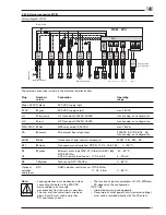
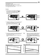
5.4.2 Continued program sequence
The continued sequence can be found in the sequence
diagram on the right.
Display
Sequence diagram
Flame signal
Ignition
V1 / V2
Heat demand
Flame stabilisation period
Safety period
Ignition
speed
Modulating
operation
Post purge
speed
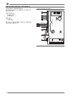
15 = WTC 15-A
25 = WTC 25-A
32 = WTC 32-A
P1 = Calorifier control 1
P2 = Calorifier control 2
P3 = Calorifier control 3
P = Boiler circuit pump with PWM
control
- = 3 stage pump
A = External sensor available
t = Temperature remote control
4 - 20 mA (N1)
- = Connection B3/N1 not used
H = Version -H, -H-0
C = Version -C
W = Version -W
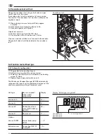
Display “Unit configured”
The unit carries out 5 ignition attempts.
After the fifth unsuccessful attempt the display shows the
code F21. Initiate a restart by pressing the reset button.
Switch on WTC at the mains switch.
During the first 10 seconds an analysis of the sensors
and actuators connected is carried out.
The WCM-CPU displays the configuration detected in
flashing codes.
If a calorifier or de-couple sensor has been detected by
the WCM-CPU the relevant control variation will be
displayed after approx. 7 seconds instead of the boiler
type.
The configuration detected is displayed flashing for
approx. 20 seconds.
By pressing the button during this time the
configuration is saved.
☞
If the
button is not pressed, an automatic backup
is carried out after 24 hours. If there is a power failure
before this time has elapsed, the sequence starts
again.
☞
The configuration can be changed manually
(description in Ch. 6.3.3; parameter P10).
☞
Complete detection is only carried out when the
unconfigured unit is turned on.
A configured unit shows its saved configuration when
switched on.
If, for example, an external sensor is fitted at a later
stage, the WCM shows this new configuration with
flashing codes when switched on.
The continuing procedure corresponds to that of an
unconfigured unit.
Display control variations
P1 = Control with one calorifier sensor ( Ch. 7.6.5)
P2 = Control with two calorifer sensors ( Ch. 7.6.6)
P3 = Control for hydraulic de-couple ( Ch. 7.6.7)
Содержание thermo condens WTC 15-A
Страница 92: ...92 Notes A ...
Страница 93: ...93 A ...

