


40
Manual maxGUARD
2526740000/02/03.2018
6 Electronic load monitors
| AMG ELM-Qxxxx
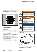
6.4
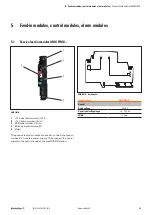
AMG ELM-Qxxxx
AMG ELM-Qxxxx
1
+24 V main strand connection (+24 V)
2
LED
3
Reset button “R”
4
PLUS output connection (cross-connector)
5
GND main strand connection (0 V)
6
PLUS output connections (2.5 mm
2
)
7
Markers
8
Internal signal line connection
The AMG ELM-Qxxx 4-channel electronic load monitors
monitor individual load circuits and disconnect them in the
event of a short circuit or overload. The tripping current and
the tripping characteristic are fixed.
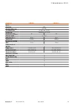
LED
Colour
Meaning
LED
Green
Fault-free operation
Red
Load monitor switched off
Red, flashing
Load monitor tripped
Red, flashing fast
Internal error
Orange (red and green) Overtemperature detected
Red, green, alternating Reset button deactivated for 30 seconds
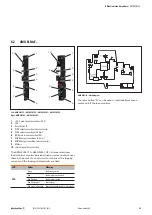
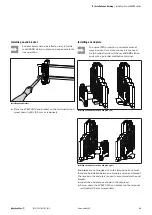
OUT n+
OUT n+
AMG ELM-Qxxxx block diagram (illustration of individual channel)
The reset button “R” can be used to individually reset and
switch on/off the load monitors.
The 4-channel load monitors have two plus outputs per
channel. The minus potential for the connected load circuits
must be provided via potential distribution terminals.


