


33
Manual maxGUARD
2526740000/02/03.2018
5 Feed-in modules, control modules, alarm modules
| Alarm modules AMG AM...
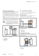
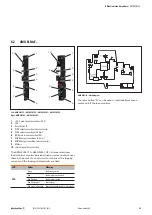
5.4 Alarm modules AMG AM...
AMG AM...
1
+24 V main strand connection (+24 V)
2
LED alarm
3
LED overload advance warning
4
I>90% connections (2.5 mm
2
)
5
GND main strand connection (0 V)
6
Alarm connections (2.5 mm
2
)
7
Markers
8
Internal signal line connection
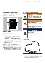
Alarm signals and overload advance warnings can be trans-
mitted potential-free to control boards using alarm modules.
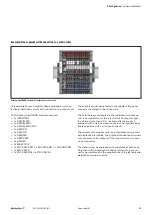
LED
Colour
Meaning
AL
Red
Alarm tripped
I >
Yellow
Overload advance warning (I > 90%)
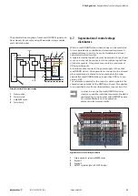
AMG AM... block diagram
Signal Function
Relay NO contact
I>90%
Overload advance warning
K1 closed: I < 90% I
T
K1 open: I > 90% I
T
Alarm
Load monitor tripped
K2 closed: no alarm
K2 open: alarm
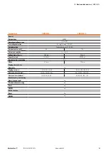
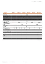
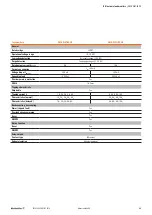
Technical data
AMG AM...
General
Rated voltage
24 V DC
Operational voltage range
18 – 30 V DC
Low voltage detection
Yes (supply voltage < 18 V DC)
Surge detection
Yes (supply voltage > 31.2 V DC)
Operating current consumption
100 mA
Width
12.2 mm
Relay outputs
Contact type
NO contact
Permissible contact load
30 V/100 mA


