


7
Manual maxGUARD
2526740000/02/03.2018
3 System overview
| Mode of operation and connection concept
3.1 Mode of operation and connection concept
AMG FIM-0
AMG CM
AMG ELM
AMG OD
AMG FIM-0
AMG CM
AMG ELM
AMG OD
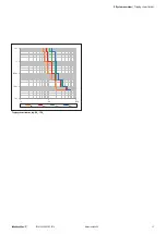
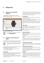
Left: Main strands and load outputs (red: +24 V, blue: 0 V)
Right: Communication via the internal signal line (orange)
A maxGUARD station has three main internal connection
channels:
–
+24V main strand for +24 V potential
–
GND main strand for 0 V potential
–
Internal signal line for communication
The two main strands are connected to the power supply via
a feed-in module and distribute the respective potentials for
the entire maxGUARD station.
The electronic load monitors form parallel junctions originat-
ing from the main strands.
Potential distribution terminals may be used to replicate the
outputs of the load monitors as required.
The internal signal line enables communication within the
maxGUARD station. Active feed-in modules, control modules
and alarm modules connect the internal signal line to an ex-
ternal control board.
All connections between the modules of a maxGUARD sta-
tion are established using cross-connectors.
The main connection channels are designed as double
channels. For high currents, the main strands must each be
equipped with two cross-connectors (see section 4.4). If nec
-
essary, the maxGUARD station can be extended by interleav-
ing the placement of the cross-connectors.
If a module cannot be connected to a specific main connec
-
tion channel, the corresponding cross-connection contacts
will not be available. Installed cross-connectors will subse-
quently not be connected to the module and the individual
contact elements of the cross-connectors do not have to be
removed. White markings on the plastic tabs of the modules
indicate the active cross-connection sockets.


