12” to 18” apart.
FOR FULLY ADJUSTABLE TRACK:
For the header, align the weatherstrip 1/8” to 1/4” inside
the header edge, and temporarily secure it to the header with equally spaced nails. Starting
at either side of the jamb, fit the weatherstrip up tight against the temporarily attached
weatherstrip in the header and 1/8” to 1/4” inside the jamb edge. Temporarily secure the
weatherstrip with equally spaced nails. Repeat for other side. This will keep the bottom sec-
tion from falling out of the opening during installation. Equally space nails approximately 12”
to 18” apart.
HEADROOM REQUIREMENT:
Headroom is defined as the space needed above the top of
the door for tracks, springs, etc. to allow the door to open properly. If the door is to be motor
operated, 2-1/2” (64 mm) of additional headroom is required.
NOTE:
6” low headroom conversion kit is available for 12” radius only. Contact your local
Wayne Dalton dealer.
BACKROOM REQUIREMENT:
Backroom is defined as the distance needed from the opening
back into the garage to allow the door to open fully.
BACKROOM REQUIREMENTS
Door Height
Track
Manual Lift
Motor Operated
6’0” to 7’0”
6” Low Headroom
103-1/2” (2629 mm)
125” (3175 mm)
7’1” to 8’0”
115-1/2” (2934 mm)
137” (3480 mm)
8’1” to 9’0”
127-1/2” (3239 mm)
168” (4267 mm)
9’1” to 10’0”
139-1/2” (3543 mm)
168” (4267 mm)
10’1” to 12’0”
163-1/2” (4153 mm)
See *NOTE
12’1” to 14’0”
187-1/2” (4763 mm)
See *NOTE
HEADROOM REQUIREMENTS
Track Type
Space Needed
6” Low Headroom
8-1/2” (216 mm)
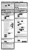
Weatherstrips
Level heade
r
Finished
Door width
Jamb
s
Backroo
m
Plumb
jambs
Finished
Door
Height
Nail
Headroom
Header board 2”x 6”
lumber preferred
Suitable mounting surface
2”x 6” lumber minimum
Min. Side
room
Clearance
is 3 1/2”
Min. Side
room
Clearance
is 3 1/2”
1/8” to 1/4”
1/8” to 1/4”
Other track systems
Weather
seal
Jamb
Door
Stop
Jamb
Door
Stop
Jamb
Weather
seal
Jamb
Quick Install track
Package Contents
NOTE:
Depending on the door model, some parts listed will not be supplied if not required.
Rear Back Hangs may not be included with your door.
Door sections (as required)
Torsion shaft or Torsion keyed shaft (as required)
Torsion keyed shafts (as required)
Horizontal tracks RH/LH
Quick Install flag angles RH/LH (as required)
Vertical tracks RH/LH (as required)
Fully Adjustable flag angles RH/LH (as required)
Riveted vertical track assemblies RH/LH (as required)
Wall angle track assemblies RH/LH (as required)
Quick install jamb
brackets (as required)
Fully Adjustable jamb
brackets (as required)
Pull down
rope (if included)
Track rollers
(as required)
Drawbar operator
bracket (if included)
Set collars
(as required)
Weatherstrips & nails
(If included)
Door stop & nails
(If included)
(2) Top fixtures
Cable drums RH/LH
Torsion springs RH/LH
Center bracket
End bearing brackets
RH/LH (as required)
Center coupler
assembly
(as required)
End bearing brackets
RH/LH (as required)
Keys
(as required)
Center bracket bearing
(as required)
(2) 3/8”- 16 Hex nuts
1/4”- 20 Flanged
hex nuts (as required)
(2) 5/16” Washers
1/4”-20 x 11/16” Self
drilling screws (as required)
1/4”-20 x 9/16”
Track bolts (as required)
Counterbalance
lift cables
1/4”-14 x 5/8” Self tapping
screws (as required)
3